Dosing dispenser

a dispenser and dosing technology, applied in the field of dosing dispensers, can solve problems such as getting “jammed”

Inactive Publication Date: 2007-07-10
BRUGGER CO
View PDF14 Cites 18 Cited by
  • Summary
  • Abstract
  • Description
  • Claims
  • Application Information

AI Technical Summary

Benefits of technology

[0007]In contrast to this, the invention is based on the object of providing a dosage dispenser which i

Problems solved by technology

However, the pump units or their pump plungers can be subjected to considerable tilting and/or twisting moments w

Method used


Image

  • Dosing dispenser
  • Dosing dispenser
  • Dosing dispenser

Examples


Embodiment Construction

[0011]This object is achieved by a dosage dispenser in accordance with the features of claim 1. Preferred embodiments are the subject matter of the sub-claims.

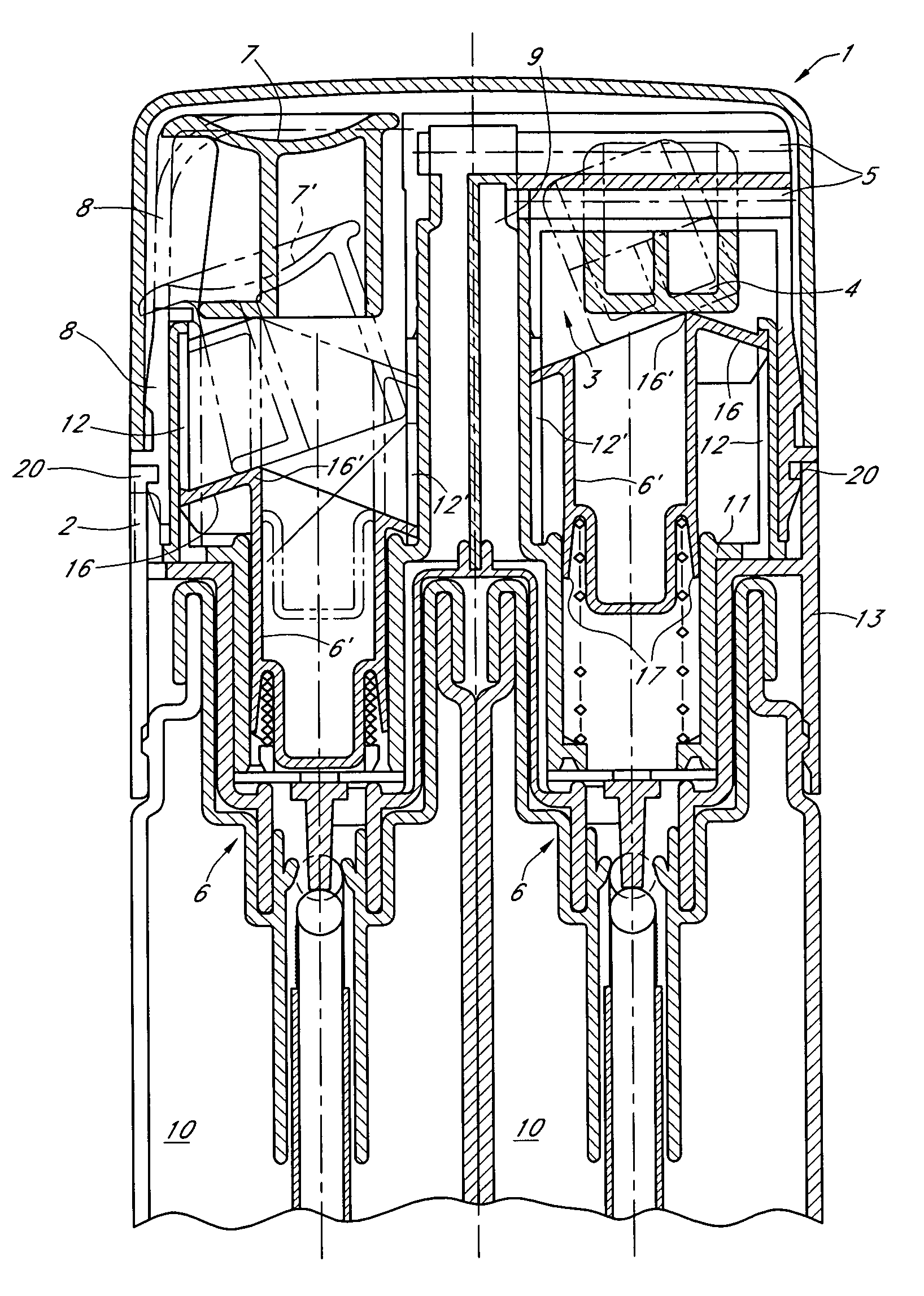
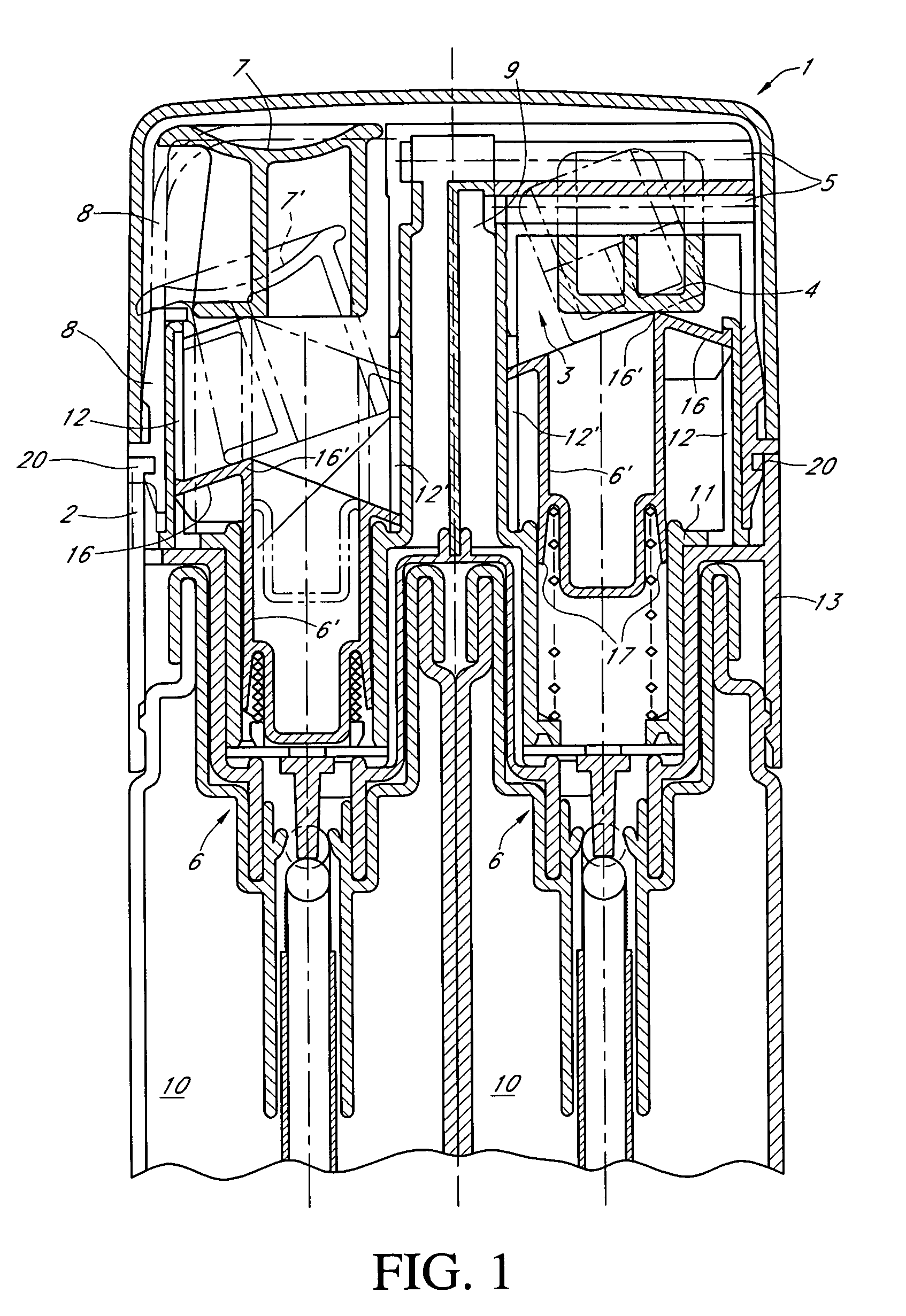
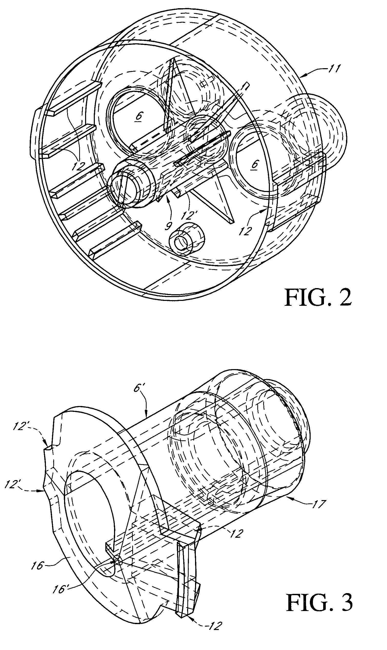
[0012]In comparison with the dosage dispensers as described above, the solution in accordance with the invention has a substantially simpler and more stable configuration because the pump unit comprises in its upper region a guide means which is resistant to tilting and twisted, and especially comprises a collar formed thereon. This arrangement allows the guidance of the pump plunger to be executed in a substantially more stable manner than the configurations as described above and the number of movable components can be reduced. Preferably, the collar is formed integrally with the respective pump plunger. In particular, it is configured as an injection-molded part.

[0013]An especially advantageous aspect is that a guide rail is provided radially each on the inside and outside for guiding the pump plunger of the dosage dispense...


PUM


Abstract

According to the invention, a dosing dispenser of simple construction, for the dosing of components held in a reservoir section by at least one pump unit connected thereto and an adjuster element, which may be pivoted about a horizontal axis by a handle for operation of a pump piston of the pump unit and about a vertical axis for adjustment of the amount ratios of the components may be produced. The pump piston comprises at least one guide for a non-tipping and/or non-rotating mounting in the upper region thereof. A particularly stable operation of the pump piston may thus be guaranteed.

Description

BACKGROUND OF THE INVENTION[0001]1. Field of the Invention[0002]The invention relates to a dosage dispenser according to the preamble of claim 1.[0003]2. Description of the Related Art[0004]Dosage dispensers are known from EP 0 755 721 A2 and DE 198 18 434 in which the mixing ratio of two pasty or fluid components can be adjusted in a continuous manner. Such a dosage dispenser can be used advantageously as a dispenser for sun lotion in order to mix two sun lotion components with a sun lotion factor of 1 and of 25 for example, so that the sun lotion factor can be set in a continuous manner in the region of 1 to 25. Said dosage dispenser represents a substantial improvement for the consumer because the consumer can choose the sun lotion factor pending on the insulation and the acclimatization of the skin and the consumer does not have to carry several containers with different sun lotion factors around with him.[0005]Even in the further development of the proposed solution according t...

Claims


Application Information

Patent Timeline
IPC IPC(8): B67D5/52B67D7/58B05B11/00B67D7/70
CPCB05B11/3083B05B11/3084B05B11/1083B05B11/1084
Inventor BRUGGER
Owner BRUGGER CO
Why Eureka
Try Eureka