
Apparatus for trapping emboli

a technology of emboli and apparatus, applied in the field of filters, can solve the problems of reducing the flow of blood to the brain with obvious negative consequences, affecting the treatment effect, so as to prevent the separation of parts of the apparatus

Inactive Publication Date: 2007-07-10
MEDTRONIC VASCULAR INC
View PDF69 Cites 33 Cited by
  • Summary
  • Abstract
  • Description
  • Claims
  • Application Information

AI Technical Summary

Benefits of technology

The filter effectively traps both micro- and macro-emboli while being easily deployable and retractable through the same catheter, reducing patient discomfort and procedural complexity, with safety features to prevent filter components from breaking off.

Problems solved by technology

When the blockage occurs in the coronary arteries which feed the heart, a heart attack can result.
Similarly, blockages in the carotid arteries can restrict the flow of blood to the brain with obvious negative consequences.
These blockages are often found in locations that are difficult to access.
One of the dangers associated with this procedure is that a part of the plaque could break off and enter the patient's blood stream during treatment.
These materials are often too large to pass easily through the body's capillaries and can become lodged therein and block the flow of blood.
If the blockage occurs in the brain or the lungs, it can be harmful or even fatal.
This makes this filter difficult to use and creates additional discomfort for the patient.
However, it is often desirable to remove the filter after a procedure is complete, and this would not be practicable using the Simon filter.
In addition, the wire mesh strainers disclosed in these patents might be capable of stopping relatively large pieces of material, such as those generated when a plaque is severed from an arterial wall by a cutting instrument, but are not suitable for stopping the micro-emboli that can occur during a balloon angioplasty procedure.
Neither these nor any other known devices provide a simple and effective option for dealing with such micro-emboli while at the same time functioning to block any larger pieces of material that might break free.

Method used


Image

  • Apparatus for trapping emboli
  • Apparatus for trapping emboli
  • Apparatus for trapping emboli

Examples


Embodiment Construction

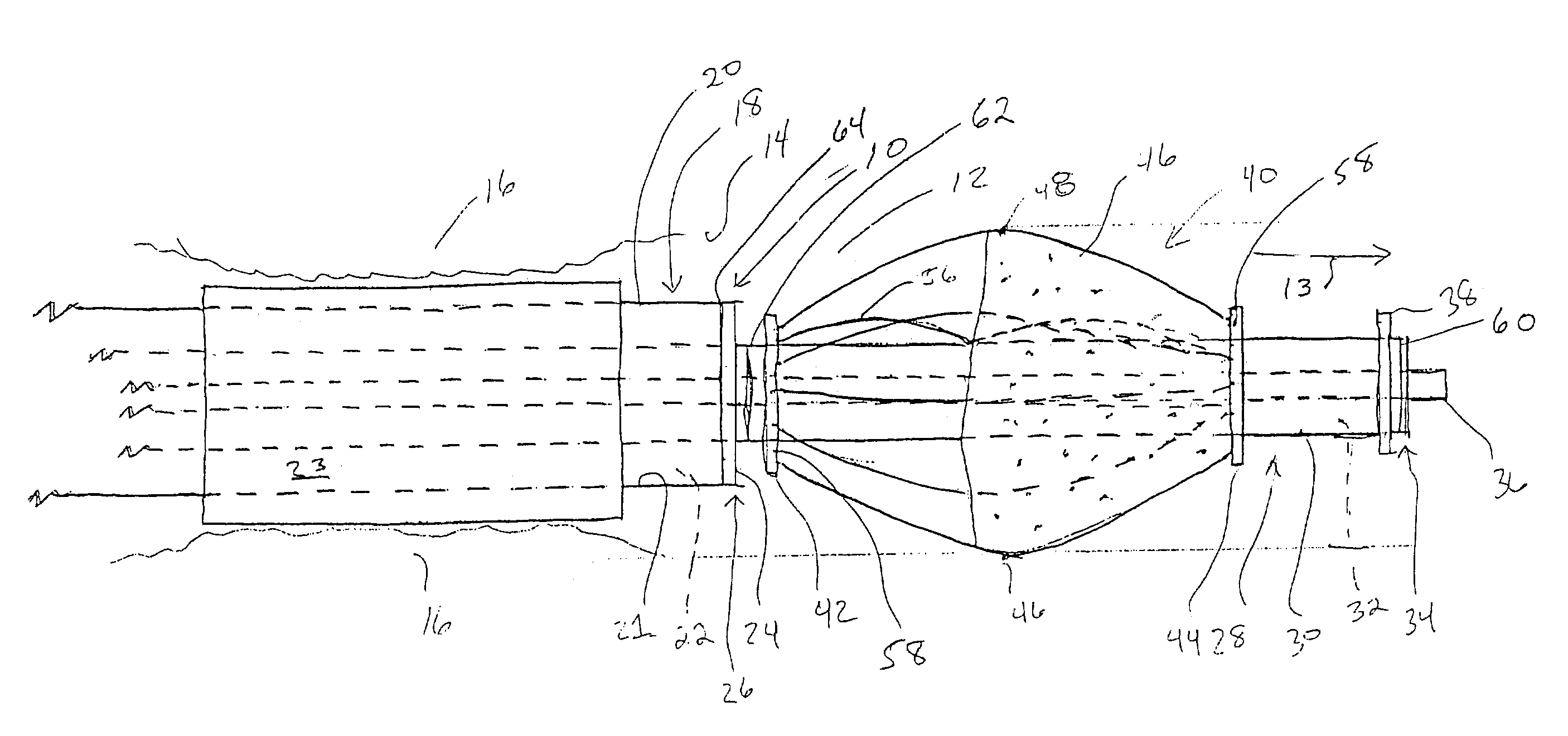
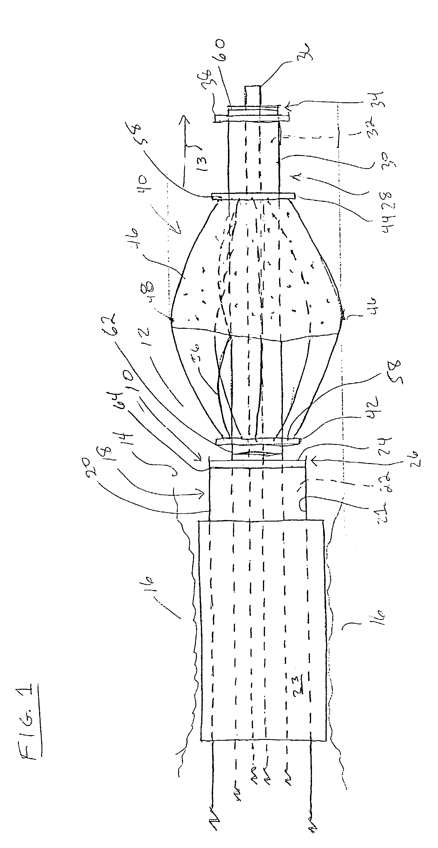
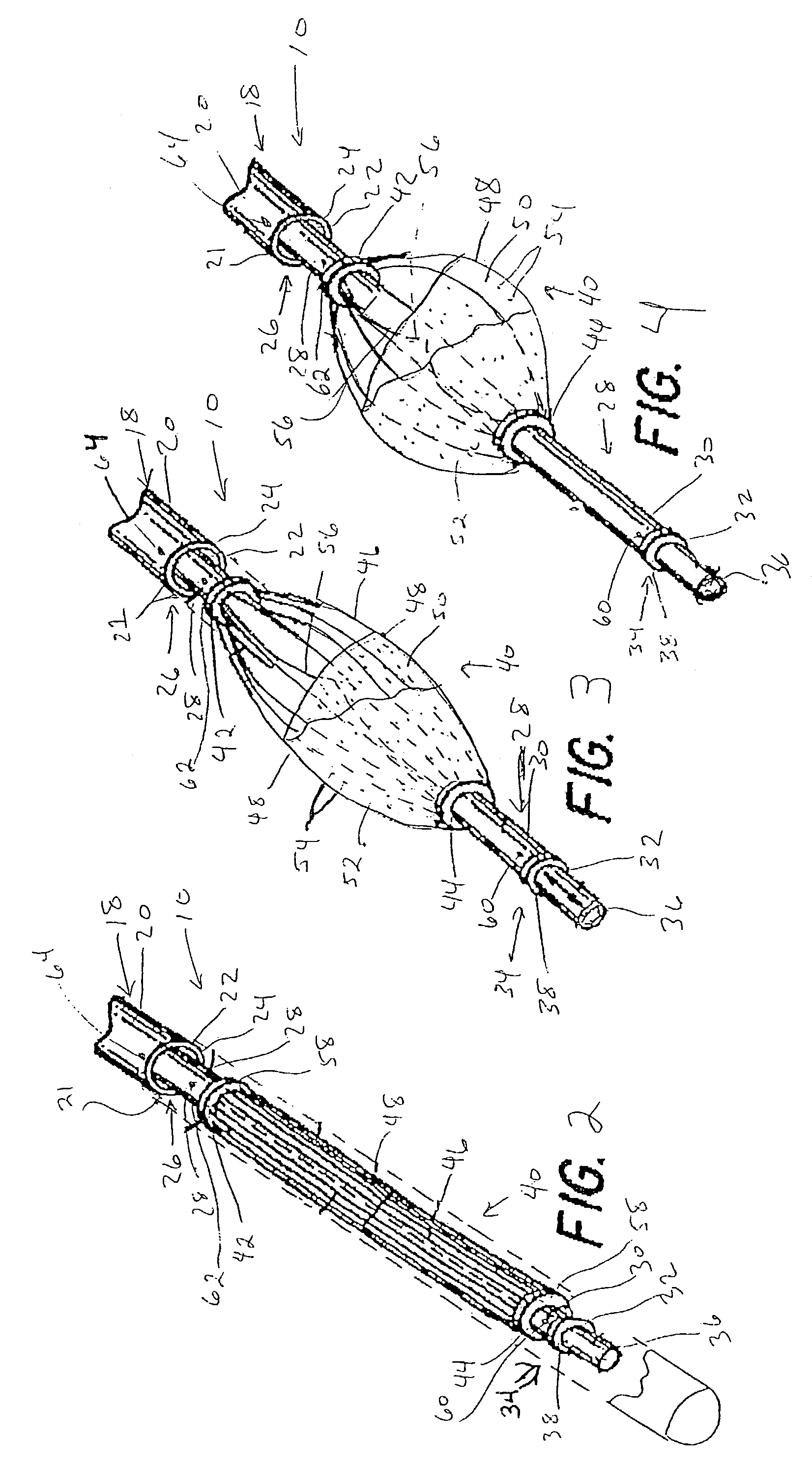
[0028]Referring now to the drawings, wherein the showings are for the purpose of illustrating a preferred embodiment of the subject invention only and not for the purpose of limiting same, FIG. 1 shows a balloon catheter assembly designated generally by the numeral 10 positioned within an artery 12 having walls 14 wherein blood flows in the direction of arrow 13. Plaques 16 on walls 14 decrease the diameter of artery 12, and the purpose of the angioplasty procedure is to compress plaques 16 against walls 14 to increase the blood flow through artery 12. Catheter assembly 10 comprises a balloon catheter 18 having an outer wall 20, an inner wall 21, a lumen 22 and a distal end wall 24 at its distal end 26. (In this description, the term “distal” refers to the end of the catheter assembly deep within the patient's body and the term “proximal” refers to the end of the assembly outside of the patient's body). A balloon 23 is connected to outer wall 20 of catheter 18 and is equipped with s...


PUM


Abstract

A filter for filtering micro-emboli from a patient's blood during an angioplasty procedure is disclosed which comprises a plurality of curved wires connected to a rod between a first connector fixed with respect to the rod and a second connector slidingly mounted on the rod. Two layers of filter material are connected to opposite sides of the wires, and each layer includes perforations which are offset from the perforations in the other layer. When the rod and the wires are disposed within a catheter, the inner wall of the catheter compresses the wires toward the rod and when the rod is extended from the catheter, the wires resume their curved shape and pull the sliding connector along the rod toward the fixed connector.

Description

CROSS-REFERENCE TO RELATED APPLICATIONS[0001]This application is a continuation of U.S. application Ser. No. 09 / 511,192, filed on Feb. 23, 2000 now U.S. Pat. No. 6,761,727, which is a continuation of U.S. application Ser. No. 08 / 921,345, filed on Aug. 29, 1997 and issued on May 9, 2000 as U.S. Pat. No. 6,059,814, which is a continuation-in-part of U.S. application Ser. No. 08 / 867,531, filed Jun. 2, 1997 now abandoned.FIELD OF THE INVENTION[0002]The present application is directed toward a filter, and more specifically, toward a filter for use during a catheterization procedure for filtering blood downstream of the procedure site.BACKGROUND OF THE INVENTION[0003]Arteriosclerosis is a condition in which plaques develop on the inner walls of blood vessels and restrict the flow of blood there through. Organs downstream of this constriction can be starved of oxygen, and the heart must work harder to pump blood through a circulatory system that includes such blockages. When the blockage o...

Claims


Application Information

Patent Timeline
Patent Type & Authority Patents(United States)
IPC IPC(8): A61M29/00A61B17/22A61F2/01
CPCA61B17/221A61F2/01A61F2/013A61B2017/2212A61F2002/011A61F2230/008A61F2002/018A61F2230/0006A61F2/011A61F2/0108
Inventor LADD, WILLIAM GREGORY
Owner MEDTRONIC VASCULAR INC
Learn More