
Continuous, wide-range frequency synthesis and phase tracking methods and apparatus

a wide-range frequency and phase tracking technology, applied in the direction of oscillator generators, pulse automatic control, electrical equipment, etc., can solve the problems of difficult clock synchronization, difficult alignment of clock signals, and common pll circuitry that is often poorly suited to optical systems

Inactive Publication Date: 2007-07-10
MARVELL INT LTD
View PDF4 Cites 6 Cited by
  • Summary
  • Abstract
  • Description
  • Claims
  • Application Information

AI Technical Summary

Benefits of technology

[0011]The invention therefore advantageously allows continuous adjustment of clock signal frequency and phase. The adjustment is very precise and can be performed across a wide range of frequencies, making it well suited to applications like optical data sampling where the incoming data rate varies continuously.

Problems solved by technology

Unfortunately, certain applications make clock synchronization especially difficult.
Optical systems thus give rise to the problem of aligning a clock signal to data whose frequency and phase vary continuously.
Thus, common PLL circuitry is often poorly suited to demands such as those posed by optical systems.

Method used


Image

  • Continuous, wide-range frequency synthesis and phase tracking methods and apparatus
  • Continuous, wide-range frequency synthesis and phase tracking methods and apparatus
  • Continuous, wide-range frequency synthesis and phase tracking methods and apparatus

Examples


Embodiment Construction

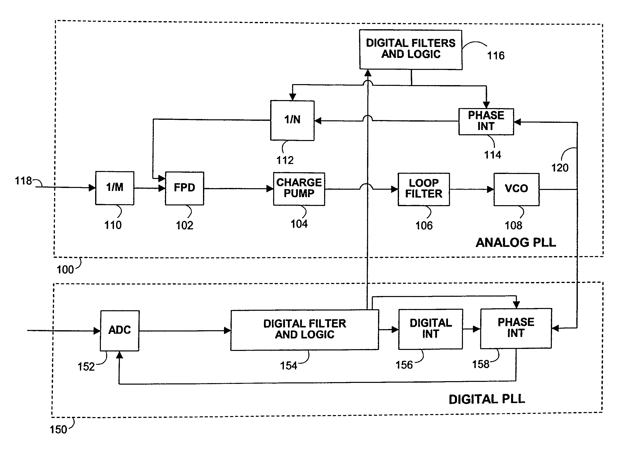
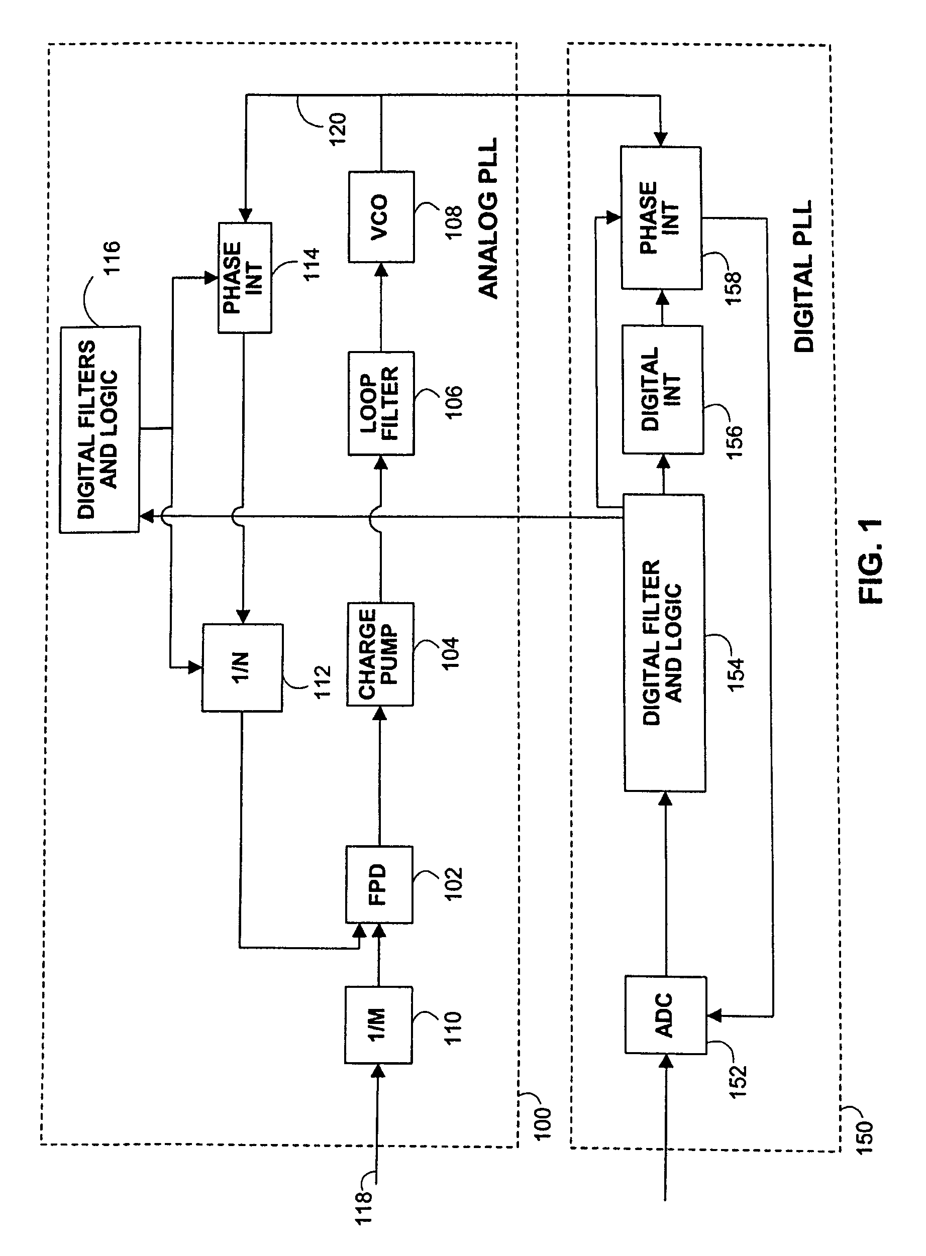
[0017]FIG. 1 shows an illustrative analog PLL 100 and an illustrative digital PLL 150 in accordance with the invention. Analog PLL 100 effectively aligns the frequency of reference clock signal 118 and feedback clock signal 120. Analog PLL 100 includes frequency / phase detector 102, charge pump 104, loop filter 106, and VCO 108, all of which work to align the two clock signals mentioned above. The operation of PLLs including circuitry such as that listed above is well known in the art, and is described, for example, in U.S. patent application Ser. No. 10 / 802,597, filed Mar. 16, 2004, which is hereby incorporated by reference in its entirety.

[0018]Analog PLL 100 also includes dividers 110 and 112, phase interpolator 114, and digital filters and control logic 116. Dividers 110 and 112 serve to scale the frequency of the output of VCO 108, which is ultimately sent to digital PLL 150. Divider 110 divides the frequency of the reference clock signal by a factor of M, while divider 112 divi...


PUM


Abstract

Circuitry and methods are provided for continuously adjustable frequency synthesis. The synthesis covers a wide range of possible frequencies and can be performed to a high degree of precision. In an embodiment of the invention, an analog phase-locked loop (“PLL”) performs relatively coarse wide-range frequency synthesis, while a digital PLL performs relatively fine narrow-range frequency synthesis and phase alignment. The analog PLL is capable of varying frequency in a stepwise linear fashion. The digital PLL communicates with the analog PLL to ensure that the output of the analog PLL is within the digital PLL's specified pull-in range.

Description

[0001]This application claims the benefit of provisional application No. 60 / 546,419, filed Feb. 20, 2004, and provisional application No. 60 / 547,727, filed Feb. 24, 2004, which are hereby incorporated by reference herein in their entireties.BACKGROUND OF THE INVENTION[0002]Clock signals are commonly used to synchronize processing, sample data, and perform general timing coordination in electrical systems. The widespread use of clock signals makes proper maintenance of their frequency and phase extremely important. The phase locked loop (“PLL”) is a well known mechanism for performing this maintenance, often aligning the clock signal with an incoming data stream.[0003]Unfortunately, certain applications make clock synchronization especially difficult. For instance, optical systems often read data from media such as compact discs (“CDs”), which store the data in circular spiral tracks. Since the reader on many such systems advances along the spiral track at a substantially constant an...

Claims


Application Information

Patent Timeline
Patent Type & Authority Patents(United States)
IPC IPC(8): H03B21/00
CPCH03L7/0991H03L7/18H03L7/23H03L7/0891H03L7/091
Inventor LI, YINGXUANSUTARDJA, PANTAS
Owner MARVELL INT LTD
Learn More