Control techniques for shut-off sensors in fuel-fired heating appliances

a technology for shutting-off sensors and heating appliances, which is applied in the direction of fire alarms, combustion failure safes, instruments, etc., can solve the problems of sensor-based combustion shutdown of controlled appliances, insatiable standard flammable vapor sensor output signal magnitude range, and weakening of sensing output signal for a given concentration of sensed flammable vapor, etc., to achieve the effect of improving the accuracy of the combustion shut-off system

Active Publication Date: 2007-07-10
RHEEM MFG CO
View PDF20 Cites 18 Cited by
  • Summary
  • Abstract
  • Description
  • Claims
  • Application Information

AI Technical Summary

Benefits of technology

[0008]In carrying out principles of the present invention, in accordance with representatively illustrated embodiments thereof, improved control techniques are provided for use in conjunction with a fuel-fired heating appliance having a combustion shut-off system in which a sensor generates an age-degradable output signal indicative of its detection of an undesirable gas or other substance and usable to preclude combustion in the appliance. From a broad perspective, the accuracy of the combustion shut-off system is improved using a method comprising the steps of providing a timer operable to output a time signal indicative of the total time the sensor has been operatively associated with the appliance, and utilizing the time signal to compensate for age-created inaccuracy in the sensor output signal.

Problems solved by technology

One design issue presented by this use of flammable vapor sensors is that the strength of their sensing output signal for a given concentration of sensed flammable vapors tends to diminish over time as the sensor “ages”.
Since the heating appliance control system typically prevents the sensor from terminating combustion (or preventing combustion initiation) in the appliance until the strength of the flammable vapor sensor output signal reaches a predetermined magnitude, the aging degradation of the sensor output signal in effect undesirably raises the concentration of flammable vapors that the sensor must be exposed to before the sensor shuts off or prevents initiation of combustion in the appliance that it protects.
Another design issue presented by the flammable vapor sensor shut-off control of a fuel-fired water heater or other type of fuel-fired heating appliance (such as a furnace or boiler) is associated with the establishment of a “range” of detected flammable vapor concentrations in which the sensor will shut down the fuel-fired heating appliance with which it is operatively coupled.
Unless the resistance signal from the flammable vapor sensor is within this standard range, the control system with which the sensor is operatively associated will not permit a sensor-based combustion shutdown of the controlled appliance.
However, in practice it has been found that this standard flammable vapor sensor output signal magnitude range is not totally satisfactory because it does not account for the speed of response for low end resistance due to temperature, etc.

Method used


Image

  • Control techniques for shut-off sensors in fuel-fired heating appliances
  • Control techniques for shut-off sensors in fuel-fired heating appliances
  • Control techniques for shut-off sensors in fuel-fired heating appliances

Examples


first embodiment

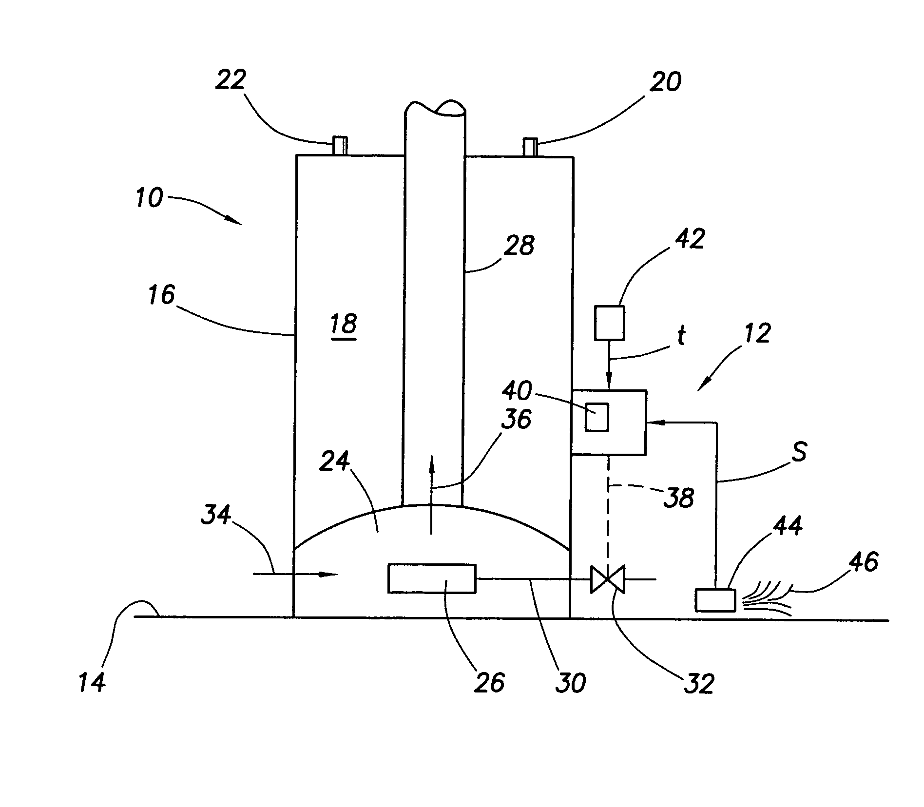
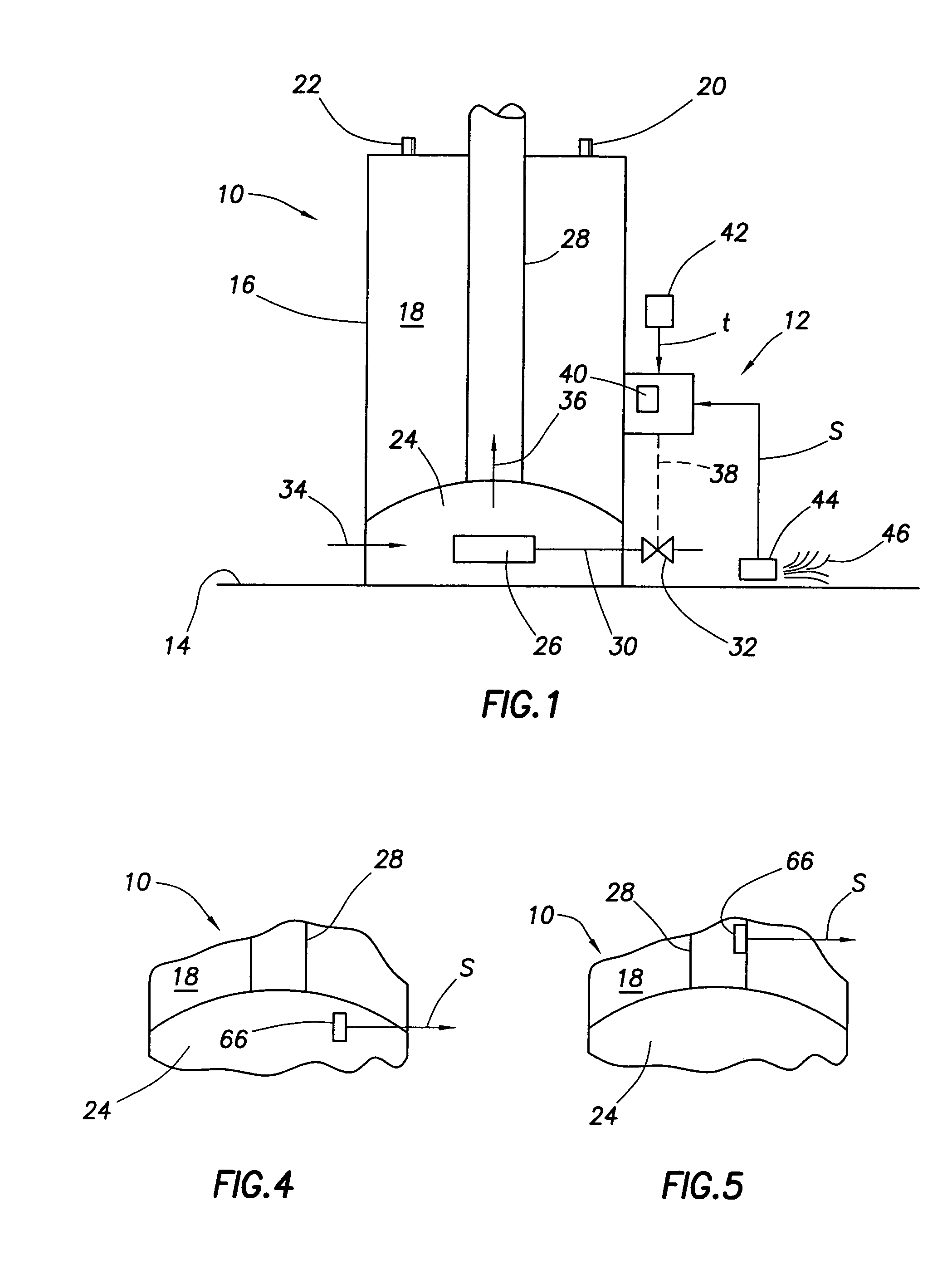
[0025]As will now be described in conjunction with the schematic flow chart of FIG. 2, in a first embodiment thereof the system 12 uniquely utilizes the signals “t” and “s” to preclude combustion within the combustion chamber 24 when the concentration of the flammable vapor 46 adjacent the sensor 44 is within a predetermined range. Importantly, according to a key aspect of the present invention, the combustion shut-off accuracy of the sensor 44 (i.e., its preclusion of appliance combustion only when the sensed flammable vapor concentration is in the preset range thereof) is substantially maintained during its entire operational life despite the unavoidable progressive lessening (degradation) of its resistance output signal “s” for a given concentration of detected flammable vapor 46 due to “aging” of the sensor caused simply by the passage of time.

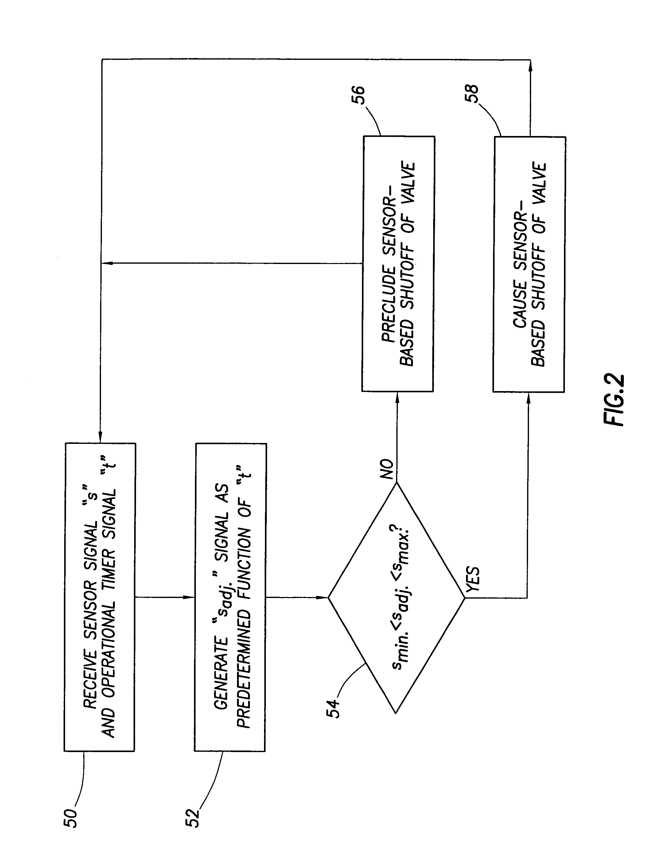
[0026]Turning now to FIG. 2, in the initial step 50 of the combustion shut-off control technique provided by the system 12, the microproc...

second embodiment

[0030]The sensor-based combustion shut-off control technique of the system 12 is schematically depicted in the flow chart of FIG. 3. In this embodiment of the system 12, the initial magnitudes of smin. (within the range of from approximately 6 kΩ to approximately 10 kΩ, preferably about 8 kΩ), and smax. (within the range of from approximately 90 kΩ to approximately 110 kΩ, preferably about 100 kΩ) are pre-programmed into the microprocessor 40. In the initial step 60 of the alternate FIG. 3 combustion shut-off control technique provided by the system 12, the microprocessor 40 receives the sensor resistance output signal “s” and the operational timer output signal “t”. In the next step 62, the microprocessor 40 adjusts the sensor valve control range smin-smax. in accordance with a predetermined relationship between “t” and the sensor resistance output signals smin. and smax. (i.e., the known relationship between the cumulative installed life Of the flammable vapor sensor 44 and its ag...


PUM


Abstract

In a flammable vapor sensor-based shut-off system of a fuel-fired water heater the sensor resistance output signal degradation caused by aging of the sensor is automatically compensated for using an operational timer having an output signal indicative of the total life of the sensor subsequent to its installation on the water heater. In one embodiment of the system, a resistance adjustment signal having a magnitude related in a predetermined manner to the timer output signal is created and added to the sensor resistance output signal. In another embodiment, the timer output signal is used to appropriately adjust the minimum-maximum received sensor signal magnitude range, based on the installed age of the sensor, which will preclude combustion in the appliance. Additionally, in each embodiment thereof the system is provided with an improved initial minimum-maximum sensor signal magnitude range. Other types of shut-off gas sensors may be alternatively utilized.

Description

BACKGROUND OF THE INVENTION[0001]The present invention generally relates to the control of fuel-fired heating appliances and, in representatively illustrated embodiments thereof, more particularly provides improved control techniques for shut-off sensors, such as flammable vapor sensors, in fuel-fired heating appliances such as water heaters.[0002]Over the past several years various proposals have been made for protecting fuel-fired heating appliances, such as water heaters, from flammable vapor ignition problems using sensors operable to shut down combustion in the appliance when flammable vapors, such as gasoline fumes, are detected near the appliance. Shut-off systems of this type have been proposed to terminate further combustion air flow to the appliance or to terminate further fuel flow thereto.[0003]One design issue presented by this use of flammable vapor sensors is that the strength of their sensing output signal for a given concentration of sensed flammable vapors tends to...

Claims


Application Information

Patent Timeline
Patent Type & Authority Patents(United States)
IPC IPC(8): G08B17/10
CPCF23M11/02F23N5/242F23M2900/11021F23N2031/18F23N2231/18
Inventor HOTTON, BRUCE A.CASTLEBERRY, WALTER T.HARRIGILL, WILLIAM T.
Owner RHEEM MFG CO
Why Eureka
Try Eureka