Switchable element

a technology of switchable elements and elements, applied in the field of switchable elements, can solve the problems of reducing the maximum speed of the device, compromising the ultimate integration density, and increasing the complexity of the system, and achieve the effect of fast switching or writing processes

Active Publication Date: 2007-07-10
INT BUSINESS MASCH CORP
View PDF2 Cites 27 Cited by
  • Summary
  • Abstract
  • Description
  • Claims
  • Application Information

AI Technical Summary

Benefits of technology

[0006]Thus, the present invention provides a switchable element, such as a memory element, logic element or sensor element with a magnetic component overcoming drawbacks of prior art memory elements, logic elements or sensor elements. The element has the advantage of being especially suited for fast switching or writing processes and for miniaturisation. The switching process is desired to exhibit a larger operating window for the switching fields. Preferably, a minimum number of leads should suffice for switching, writing and readout processes.

Problems solved by technology

This has a number of drawbacks, since the field-generating striplines are cumbersome to fabricate and the currents used to create the magnetic field can lead to heating.
Moreover, for noise reduction the striplines are often electrically insulated from the structures, so that separate lines have to be used for read-out and field generation, which increases the complexity of the system.
This approach, however, has the drawback of reducing the maximum speed of the device and requires at least one additional line per memory cell, thus compromising the ultimate integration density.
This effect in turn increases the unwanted effect of element heating and also of electromigration in the structure.
Tunnelling Magnetoresistance (TMR) stacks, which exhibit a magnetoresistance effect based on a similar physical principle as GMR, may so far not be used, since their resistance is too high to obtain the current densities necessary for switching by spin-torque.
However, due to the large energy needed for read-out and writing, GMR stacks are nowadays not considered for memory elements anymore, but rather the high-resistance TMR elements, such as NiFe / Al2O3 / Co stacks.

Method used


Image

  • Switchable element
  • Switchable element
  • Switchable element

Examples


Embodiment Construction

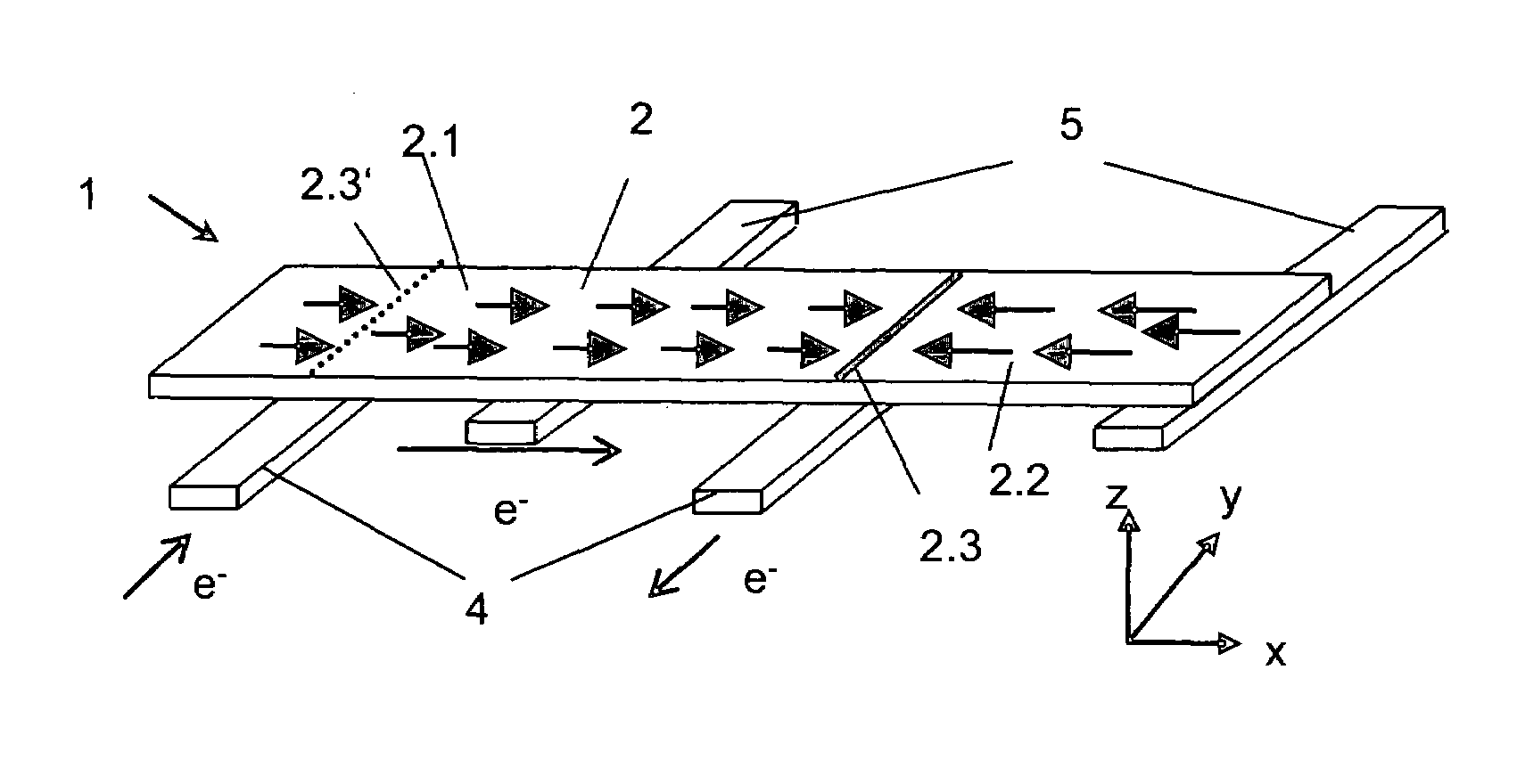
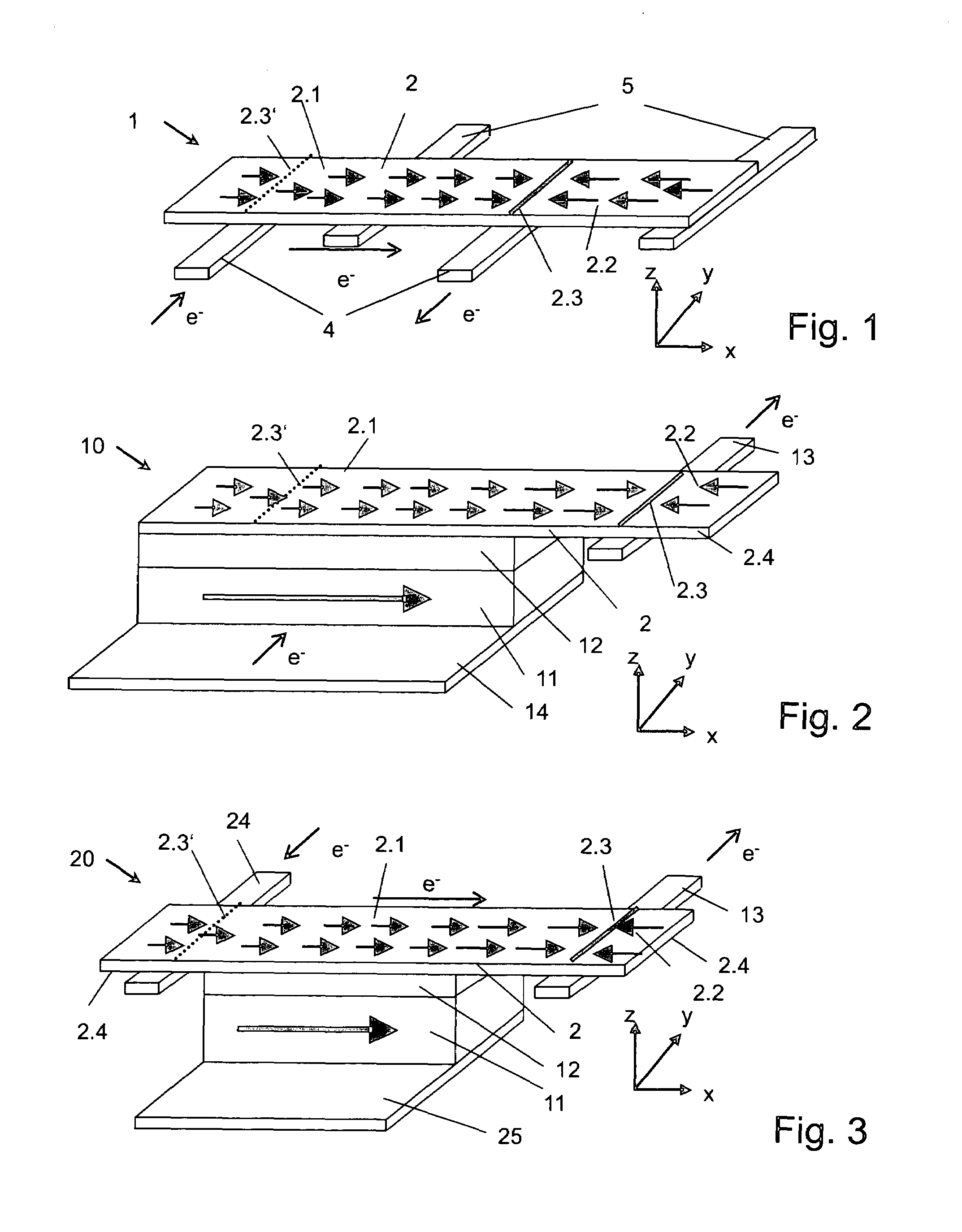
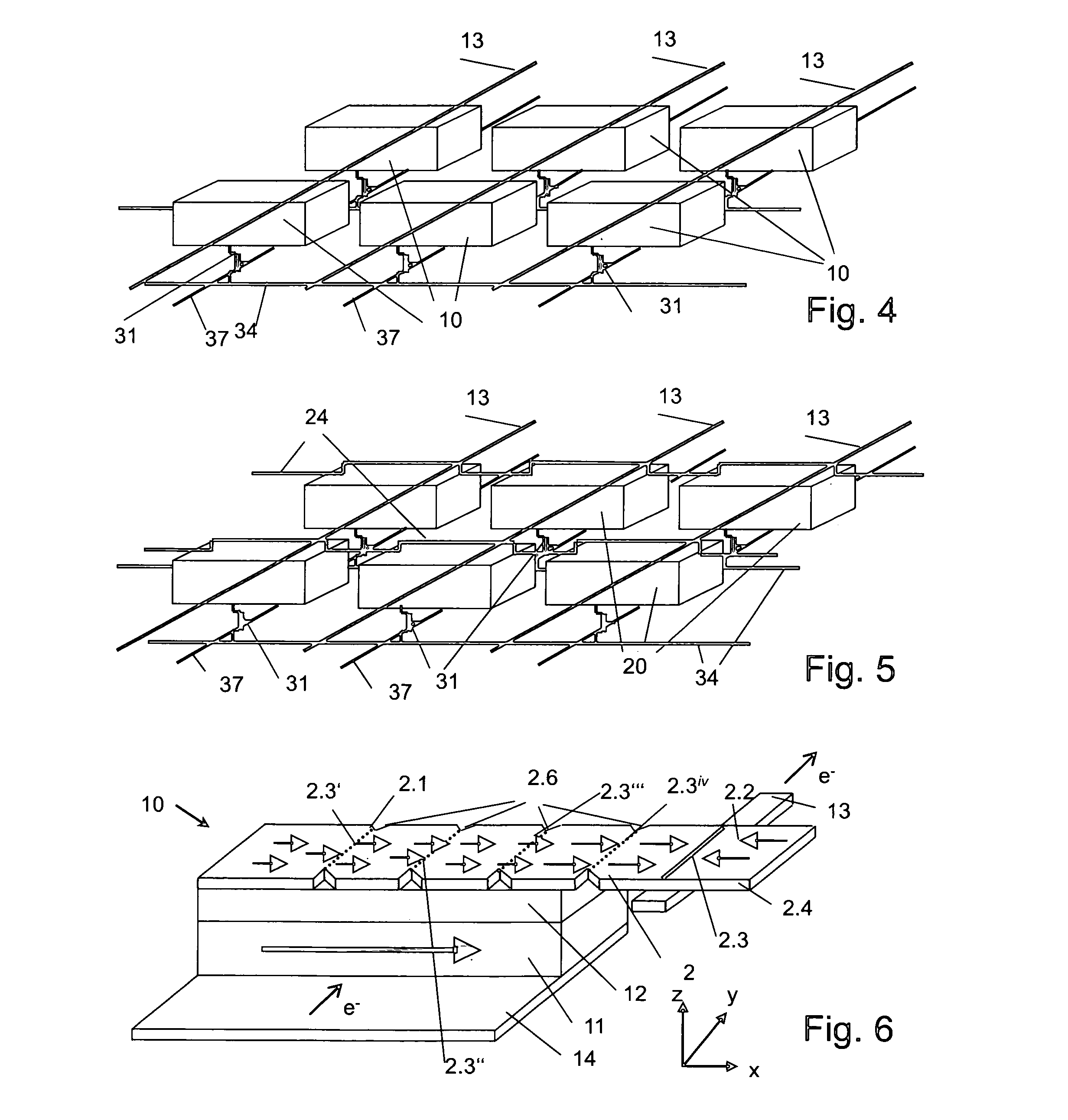
[0020]The present invention provides a switchable element, such as a memory element, logic element or sensor element with a magnetic component overcoming drawbacks of prior art memory elements, logic elements or sensor elements. The element has the advantage of being especially suited for fast switching or writing processes and for miniaturisation. The switching process is desired to exhibit a larger operating window for the switching fields. Preferably, a minimum number of leads should suffice for switching, writing and readout processes.

[0021]According to an example embodiment of the present invention, a switchable element, for example a memory element, logic element or sensor element is provided, which comprises a switchable first magnetic component exhibiting a ferromagnetic or ferrimagnetic behaviour, and comprising at least two magnetic domains with different magnetisation directions and a domain wall between the magnetic domains. The first magnetic component may be part of a ...


PUM


Abstract

A memory element, logic element or sensor element is provided, which element comprises a switchable first magnetic component exhibiting a ferromagnetic or ferrimagnetic behaviour and comprising at least two magnetic domains with different magnetization directions and a domain wall between the magnetic domains. The element has electrodes operable to induce an electric current which at least partially flows through the domain wall with a current density high enough to cause the domain wall to reversibly propagate within the magnetic component. The first magnetic component may belong to a layered system further including a second magnetic component with a fixed magnetization and a non-magnetic spacer layer arranged between the first and second magnetic component. In such a layered system, the electrical resistance may depend on the relative orientation of the magnetization directions of the first and second magnetic component, due to the GMR or TMR effect.

Description

FIELD OF THE INVENTION[0001]The invention relates to the field of devices containing ferromagnetic structures, where a number of stable and reproducibly attainable configurations (states) are used, such as in memory, logic and sensor elements.BACKGROUND OF THE INVENTION[0002]Magnetic spin switching in confined magnetic structures has applications for example in memory, logic and sensor device, in Spin-LEDs etc. Switching of a magnetic element is conventionally achieved by applying external magnetic fields, for example using a coil setup or local striplines. This has a number of drawbacks, since the field-generating striplines are cumbersome to fabricate and the currents used to create the magnetic field can lead to heating. Moreover, for noise reduction the striplines are often electrically insulated from the structures, so that separate lines have to be used for read-out and field generation, which increases the complexity of the system.[0003]Typical novel non-volatile memory devic...

Claims


Application Information

Patent Timeline
Patent Type & Authority Patents(United States)
IPC IPC(8): G11C11/22
CPCG11C11/15
Inventor KLAEUI, MATHIASALLENSPACH, ROLFJUBERT, PIERRE-OLIVIER
Owner INT BUSINESS MASCH CORP
Why Eureka
Try Eureka