Rotary valve apparatus and associated methods

a technology of rotary valves and associated methods, which is applied in the field of valves, can solve the problems of difficult to reliably and accurately conform the valve seal to the peripheral disc seating surface, many well-known problems, and difficulty in reducing the operation torque, so as to reduce the operational torque requirements, reduce the torque, and reduce the wear

Inactive Publication Date: 2007-07-17
FISHER CONTROLS INT LLC
View PDF22 Cites 13 Cited by
  • Summary
  • Abstract
  • Description
  • Claims
  • Application Information

AI Technical Summary

Benefits of technology

[0008]In carrying out principles of the present invention, in accordance with a preferred embodiment thereof, a specially designed rotary valve is provided which includes a valve body and a seal structure, carried by the valve body, for forming an elliptical seating surface. A disc is rotatably carried by the valve body and has an elliptical periphery rotatable into and out of sealing engagement with the seating surface. The elliptical disc periphery has a conical shape which creates an entrance angle on the disc seating surface that provides a variety of operational benefits including a reduction in the torque required to seat and unseat the valve disc from the associated seal structure, and a reduction in the wear on both the disc periphery and the seal seating surface. Due to the reduced operational torque requirements, the parts carrying the actuation load may be smaller, and a smaller valve actuator may be used to seat and unseat the valve disc against the associated seal seating surface. Further, broader manufacturing tolerances may be utilized in conjunction with the disc and seal structures due to a wedging effect provided by the elliptical seal and disc design.

Problems solved by technology

Although rotary valves of this general type have been utilized for many years in both fluid throttling and shut-off applications, and have been refined in a variety of manners over this time span, they are still subject to several well-known problems, limitations and disadvantages.
Because of this conventional disc configuration it is often difficult to reliably and accurately conform the valve seal to the peripheral disc seating surface without undesirably stretching the seal element to a substantial degree.
Due to this geometric seal / seat interface problem the integrity of the seal is often compromised and it is difficult to completely stop the flow of fluid through the valve.
Adjustment error, on the other hand, can seriously reduce the valve's sealing efficiency.
Another limitation present in rotary valves of conventional construction is related to the manner in which an actuator, a motorized device used to forcibly rotate the closure disc between its open and closed positions, is operatively mounted on the valve.
This overall adapter mounting structure undesirably adds to the construction cost of the overall valve assembly and makes the fabrication of the assembly more complex and time-consuming.

Method used


Image

  • Rotary valve apparatus and associated methods
  • Rotary valve apparatus and associated methods
  • Rotary valve apparatus and associated methods

Examples


Embodiment Construction

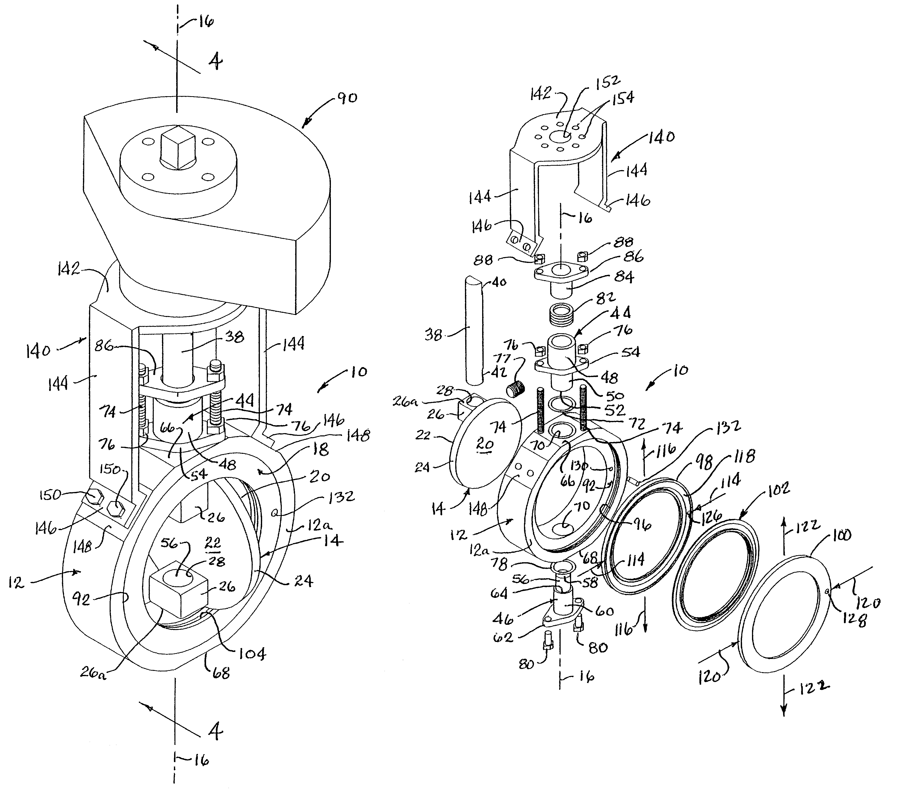
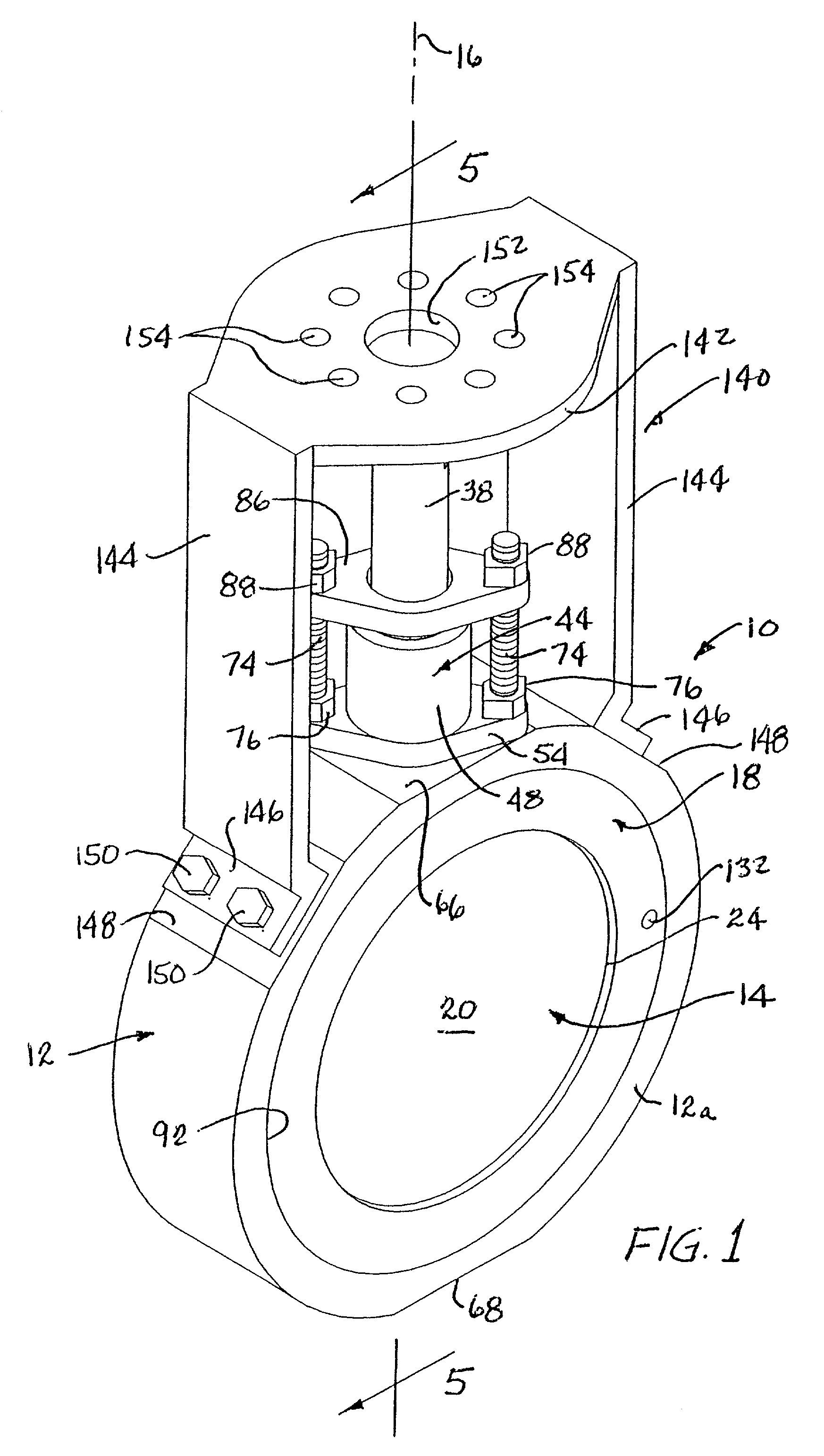
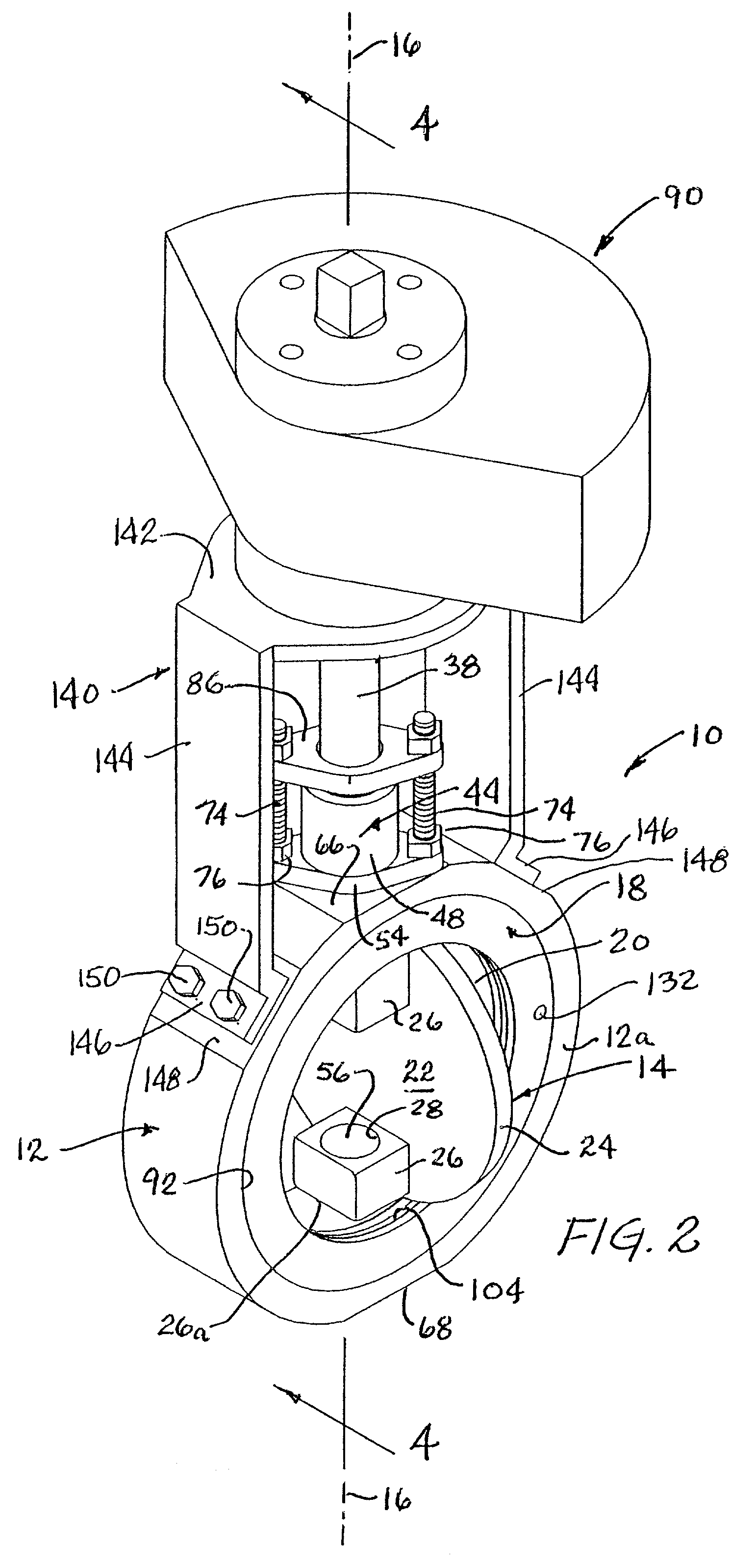
[0026]Referring initially to FIGS. 1–3, the present invention provides a specially designed rotary valve 10 (also commonly referred to as a “butterfly” valve) that incorporates therein various advantages over conventionally constructed valves of this general type. Valve 10 includes an annular metal body portion 12, a metal closure disc 14 rotatable between closed and open positions (respectively illustrated in FIGS. 1 and 2) about an axis 16 extending diametrically through the body 12, and an annular seal cartridge structure 18. With the disc 14 in its FIG. 1 closed position it cooperates with the seal cartridge structure 18 to prevent fluid flow through the interior of the body 12 and piping sections (not shown) operatively connected to its opposite sides. Alternatively, with the disc 14 in its FIG. 2 open position, fluid flow through the interior of the valve body 12, and piping operatively coupled to the valve body 12, is permitted.

[0027]Referring now additionally to FIGS. 7–8B, ...


PUM


Abstract

A rotary valve is provided with an elliptical valve disc that seats against a seal element operatively mounted in an elliptically shaped depression formed in the rigid annular portion of a seal cartridge structure carried by the valve body. Due to the elliptical shapes of the disc and corresponding seating structure, and a conical configuration of the disc periphery, sealing of the valve disc, the integrity of the seal, and the ability of the seal to completely stop the flow of fluid through the valve body are desirably improved. The centering of valve disc relative to the seal cartridge is facilitated by a specially designed disc mounting structure that eliminates any necessity of adjusting the disc along its rotational axis, and a one-piece actuator bracket is removably mounted to the valve body to substantially simplify and reduce the expense of operatively associating an actuator with the valve.

Description

CROSS-REFERENCE TO RELATED APPLICATION[0001]This application claims the filing benefit of U.S. Provisional Application Ser. No. 60 / 113,086 filed on Dec. 21, 1998 and entitled “ROTARY VALVE ASSEMBLY”, such provisional application being hereby incorporated by reference herein in its entirety, and is a divisional application to U.S. application Ser. No. 09 / 772,782 filed on Jan. 30, 2001, now U.S. Pat. No. 6,332,600.BACKGROUND OF THE INVENTION[0002]The present invention generally relates to valves and methods for fabricating them and, in a preferred embodiment thereof, more particularly relates to rotary valves, such as “butterfly” valves, and associated valve fabrication methods.[0003]Rotary valves, also commonly referred to as “butterfly” valves, are typically provided with a shut-off disc which is rotationally drivable between open and closed positions about an axis diametrically extending across the interior of a generally annular valve body. In its open position the disc permits fl...

Claims


Application Information

Patent Timeline
Patent Type & Authority Patents(United States)
IPC IPC(8): F16K25/00F16K1/226F16K27/02
CPCF16K1/2263F16K27/0218
Inventor EGGLESTON, PHILIP W.
Owner FISHER CONTROLS INT LLC
Why Eureka
Try Eureka