Power supply device and switching power supply device

a power supply device and switching power supply technology, applied in the direction of pulse technique, process and machine control, instruments, etc., can solve the problems of small power loss, low detection accuracy, and low voltage vd between the source and the drain, so as to achieve low power loss, high degree of efficiency, and high degree of accuracy

Inactive Publication Date: 2007-07-17
RENESAS ELECTRONICS CORP
View PDF5 Cites 34 Cited by
  • Summary
  • Abstract
  • Description
  • Claims
  • Application Information

AI Technical Summary

Benefits of technology

[0012]One object of the invention is to provide a switching power supply device that causes a little power loss and has a high degree of efficiency and a power supply driver circuit and a module that are suitably applied to the device.
[0013]Another object of the invention is provide a switching power supply device that can detect a current passing through a coil with high accuracy and hence can control the current with high accuracy, even if the characteristics of an output power transistor is varied by variations in manufacture and temperature, and a power supply driver circuit and a module that are suitably applied to the device.
[0014]Still another object of the invention is a switching power supply device that can detect a current passing through a coil with high accuracy and hence can control the current with high accuracy, even if the on resistance of an output power transistor is small, and a power supply driver circuit and a module that are suitably applied to the device.

Problems solved by technology

The system using a current detection resistor connected in series to a coil, as shown in FIG. 1, presents a problem that power loss is considerably large because a current passing through the coil passes through the current detection resistor just as it is.
Further, the system for detecting the voltage between the source and the drain of a power MOS transistor, as shown in FIG. 2, presents a problem that high detection accuracy can not be obtained because variations in the manufacture of a power MOS transistor and variations in detection value caused by temperature fluctuation are large.
However, in this case, for example, when a rated current of 25A is passed through a power MOS transistor having an on resistance of 2.5 mΩ, the voltage Vd between its source and drain is only approximately 60 mV, which is hard to detect.
Hence, if the voltage between the terminals of the sensing resistor is not sufficiently small as compared with the voltage Vd between the drain and the source of the power MOS transistor, the current detection MOS transistor and the power MOS transistor are different from each other in bias condition and hence a current proportional to a current passing through the power MOS transistor does not pass through the sensing MOS transistor, which results in reducing detection accuracy.
Then, the voltage between the terminals of the resistor becomes small, which presents a problem that the detection of the voltage is difficult.
Hence, when the Vout is low, a sufficient detection voltage can not be developed.

Method used


Image

  • Power supply device and switching power supply device
  • Power supply device and switching power supply device
  • Power supply device and switching power supply device

Examples


Embodiment Construction

[0036]Hereafter, the preferred embodiments of the invention will be described on the basis of the drawings.

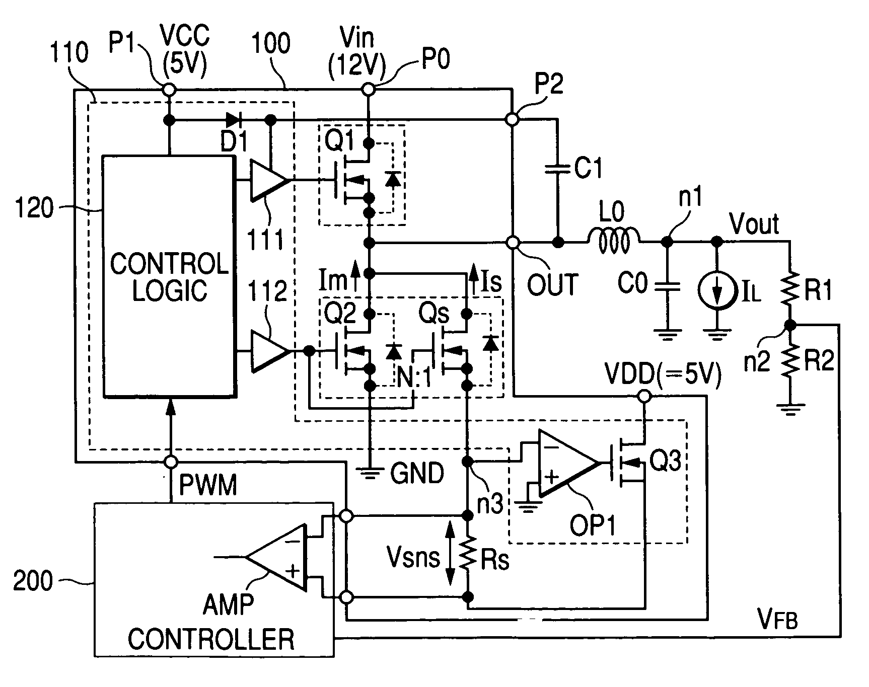
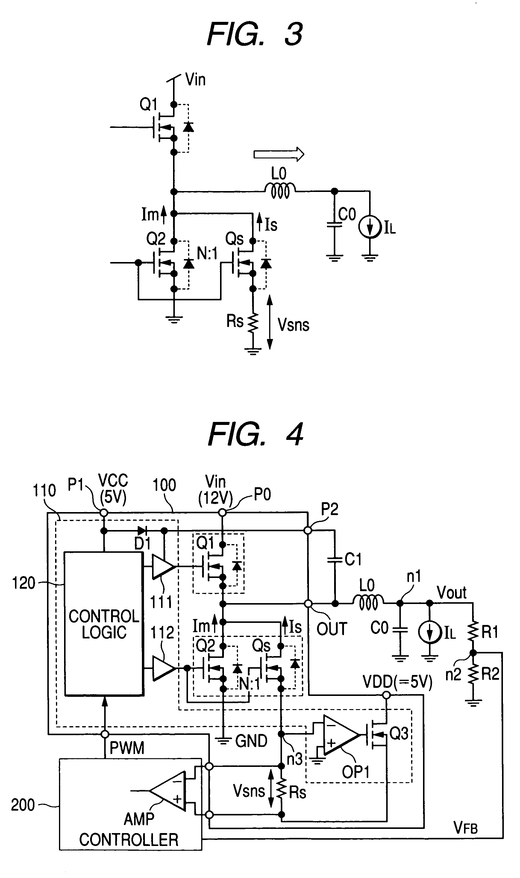
[0037]FIG. 4 illustrates the first embodiment of a power supply driver module incorporating a power supply driver circuit in accordance with the present invention and a step-down type switching regulator using the same. Here, in this specification, a unit such that a plurality of semiconductor chips and discreet parts are mounted on an insulating board such as a ceramic board, on or in which printed wirings are provided, and are connected to each other by the printed wirings or bonding wires so that the respective parts play predetermined roles, and hence are so constructed as to be handled as one electronic part is referred to as a module. This power supply driver module is molded in a package such as ceramic to make a finished product, although it is not intended to limit the module to this.

[0038]A switching regulator shown in FIG. 4 is constructed of: a power supply driver m...


PUM


Abstract

In a driver circuit constructing a switching power supply device that switches power transistors passing a current through a coil by a PWM mode, a current detection transistor, which is smaller in size than the low-potential side power transistor and a current detection resistor are provided in parallel to the low-potential side power transistor. The same control voltage as the power transistor is applied to the control terminal of the current detection transistor. An operational amplifier is formed, that has the potential of the connection node between the current detection transistor and the current detection resistor applied to its inverse input terminal and a feedback loop, so as to make a pair of input terminals of the operational amplifier be at the same potential. A signal produced by the current detection resistor is thus outputted as a current detection signal.

Description

CROSS-REFERENCE TO RELATED APPLICATION[0001]The present application claims priority from Japanese patent application No. 2004-118541 filed on Apr. 14, 2004, the content of which is hereby incorporated by reference into this application.BACKGROUND OF THE INVENTION[0002]1. Field of the Invention[0003]The present invention relates to a power supply device developing a DC voltage and to a technology effectively applied to the detection of current in a switching regulator, for example, to a power supply driver circuit for driving a power transistor constructing a switching power supply device that performs switching control by a PWM (pulse width modulation) control mode to convert an input voltage and outputs the voltage, and to a driver module incorporating the circuit, and to a technology effectively applied to the a switching power supply using the module.[0004]2. Description of the Related Art[0005]In recent years, microprocessors are mounted as system control devices in many electro...

Claims


Application Information

Patent Timeline
Patent Type & Authority Patents(United States)
IPC IPC(8): G05F3/16G01R19/00G05F1/613H02M3/155H02M3/158H03K17/08H03K17/687H03K17/695
CPCH02M3/1588H02M2001/0009Y02B70/1466H01L2224/48137H01L2224/48247H01L2224/0603H01L2924/13091Y02B70/10H02M1/0009H01L2924/00
Inventor TATENO, KOJIKUDO, RYOTAROCHIBA, SHINHOSOKAWA, KYOICHINAGASAWA, TOSHIO
Owner RENESAS ELECTRONICS CORP
Why Eureka
Try Eureka