
Magnetic resonance imaging apparatus and method wherein streak artifacts are minimized in modular k-space scanning

a magnetic resonance imaging and modular k-space technology, applied in the field of magnetic resonance tomography, can solve the problems of image artifacts, image interference in the image volume, image artifacts, etc., and achieve the effect of fast mri acquisition and streak artifacts

Active Publication Date: 2007-07-17
SIEMENS HEALTHCARE GMBH
View PDF20 Cites 103 Cited by
  • Summary
  • Abstract
  • Description
  • Claims
  • Application Information

AI Technical Summary

Benefits of technology

This approach effectively reduces streak artifacts, maintains image quality, and minimizes the impact of signal decay and eddy currents, achieving a balanced image acquisition with reduced measurement time and artifacts.

Problems solved by technology

Therefore, in many cases, only a portion of the data that are required for an artifact-free image are recorded, which is generally called “undersampling,” and, ultimately, this results in images with artifacts.
Such procedures inevitably result in image artifacts.
Such eddy currents decay with different time constants and, during this process, generate different magnetic interference fields, which then cause image interference in the image volume.
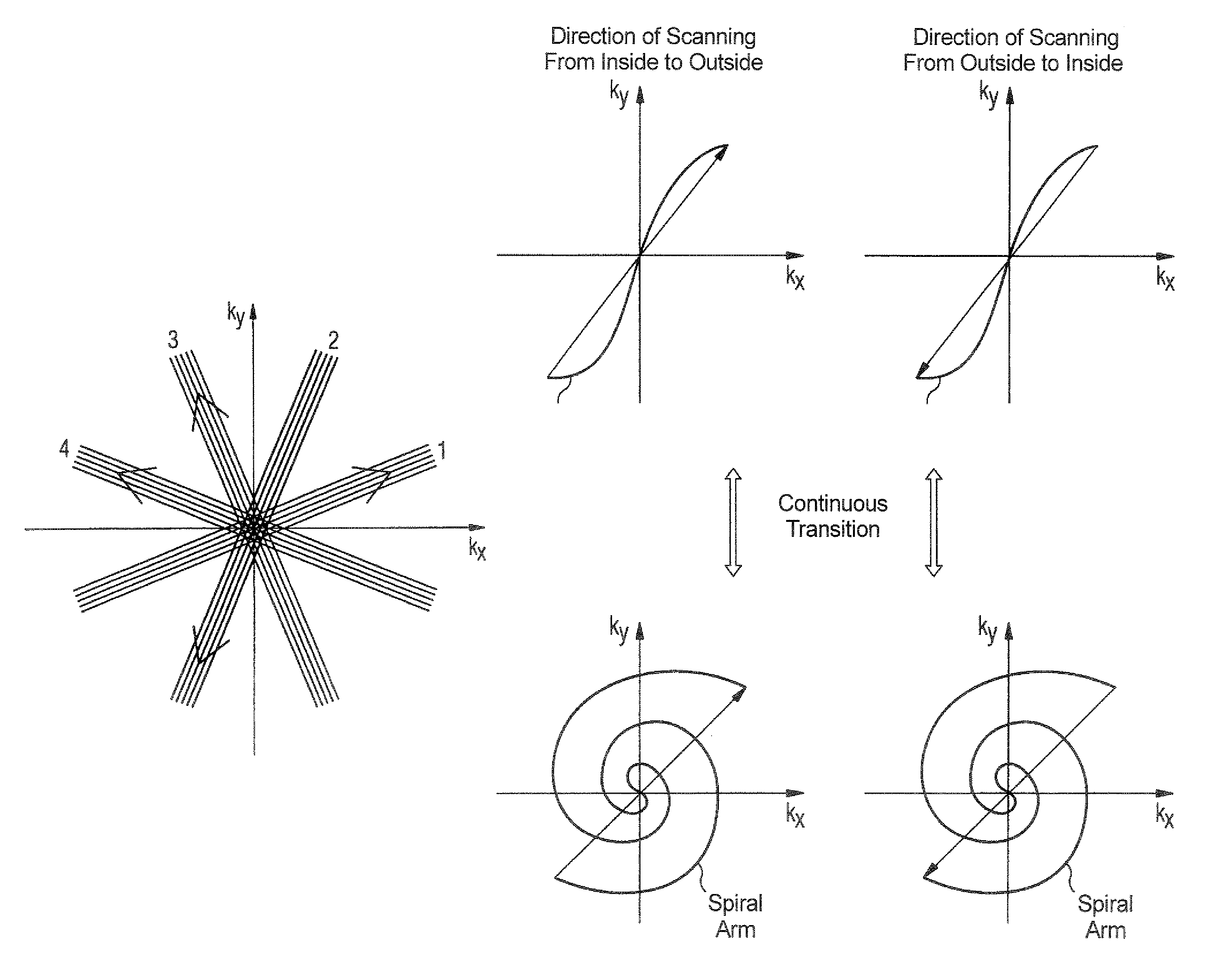
Nevertheless, with regard to the two other aforementioned image quality factors, such a scanning of k-space results in the following problems: Firstly, the “angular increment” causes the steady state of the eddy currents between the acquisition of the last projection line of the preceding measurement and the first projection line of the subsequent measurement to be interrupted, i.e., stronger eddy-current artifacts occur.
Secondly, the signal decays are not compensated for during the scanning process, which results in a strong interference with the acquisition and thus of the image quality.
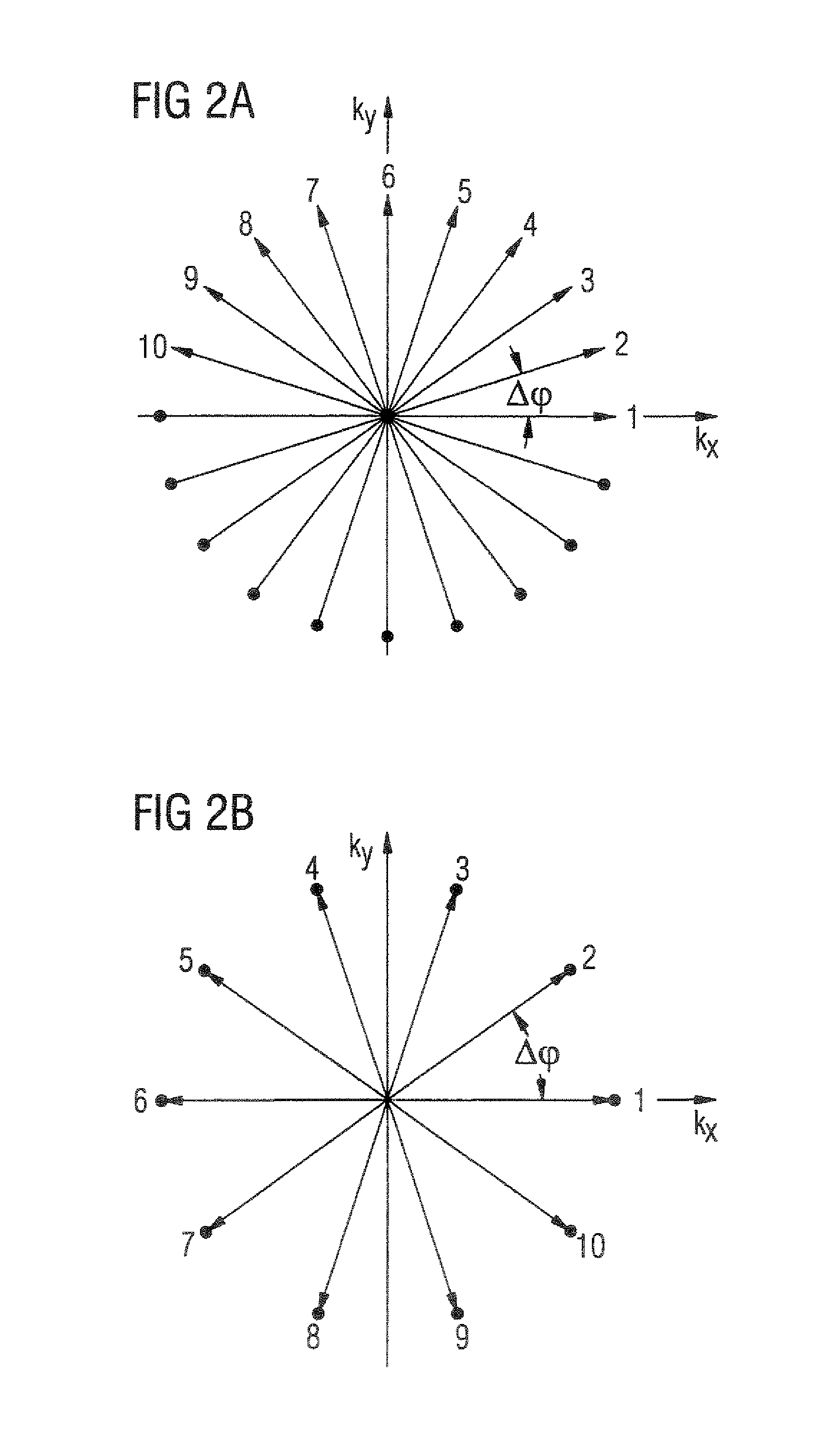
However, a serious disadvantage of this procedure is that, due to the double measurement (redundancy, see FIG. 2B) of each projection line, the artifacts-free radius R reaches only half of its possible value, so that those parts of the objects that are located farther from each other than R will strongly interfere with each other.
However, this procedure has the great disadvantage that, upon reaching the point of origin of k-space, the gradients must be switched, discontinuously and exactly, between two digitization points in order to produce the change in orientation.
The difficulty of an exact switchover increases with an increasing bandwidth per pixel (measurement point in k-space) and with an increasing size of the angular increment.
The latter is again proportional to the total number of projections, which means that this solution is difficult to implement in low-resolution real-time applications.

Method used


Image

  • Magnetic resonance imaging apparatus and method wherein streak artifacts are minimized in modular k-space scanning
  • Magnetic resonance imaging apparatus and method wherein streak artifacts are minimized in modular k-space scanning
  • Magnetic resonance imaging apparatus and method wherein streak artifacts are minimized in modular k-space scanning

Examples


Embodiment Construction

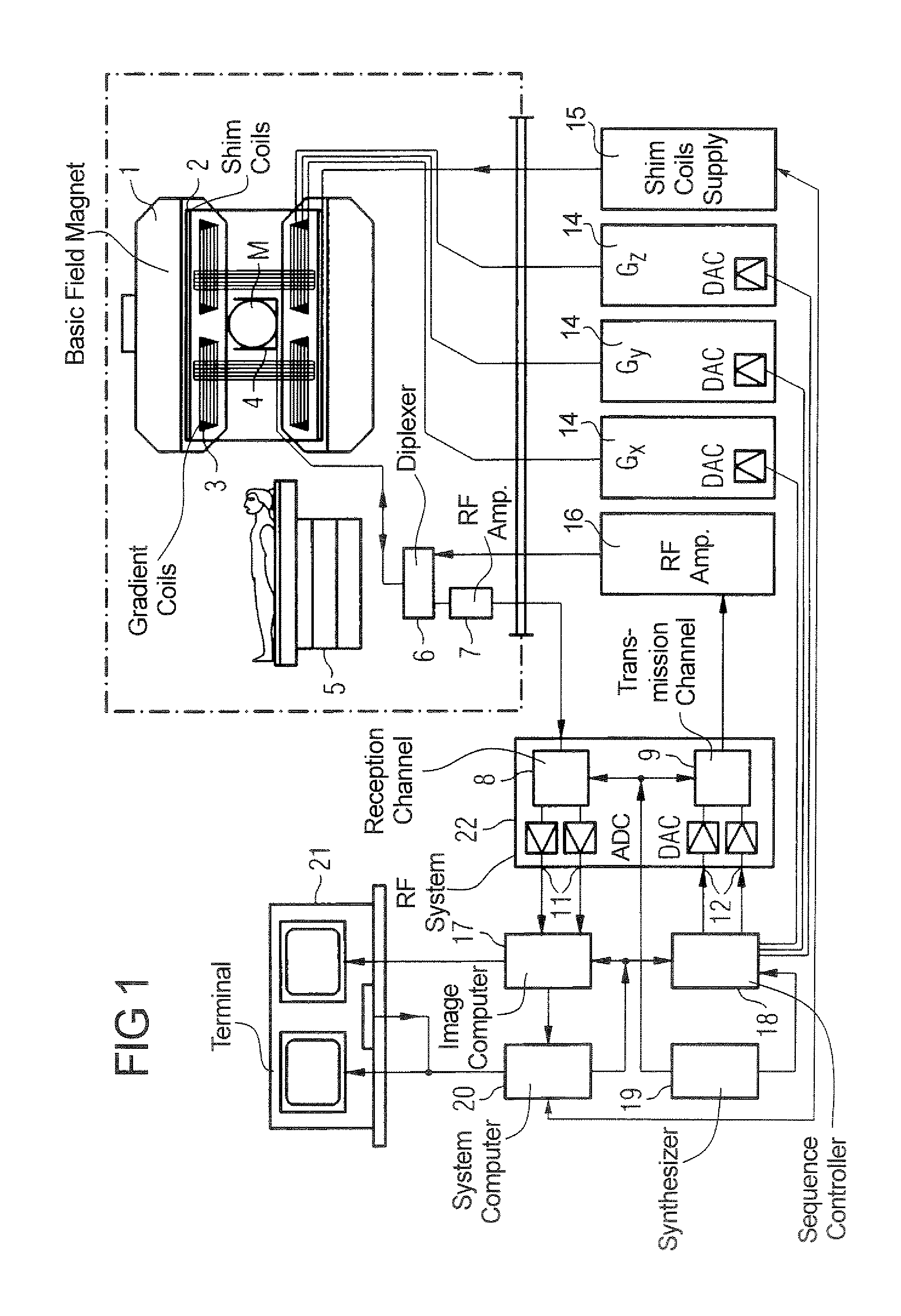
[0052]FIG. 1 is a schematic representation of a magnetic resonance imaging device for the production of a magnetic resonance image of an object according to the present invention. The basic design of the magnetic resonance imaging device conforms to a conventional magnetic resonance imaging device with the exceptions noted below. A basic field magnet 1 generates a temporally constant strong magnetic field in order to polarize, i.e., align the nuclear spins in the examination range of the object, such as, for example a part of a human body to be examined. For this purpose, a patient on a patient bed 5 is moveable into the basic field magnet 1. The high degree of homogeneity in the basic magnetic field required for magnetic resonance sampling is defined in a spherical sampling volume M, into which the parts of the human body to be examined are introduced. To support the homogeneity requirements and especially to eliminate temporally invariable influences, so-called shims, which are ma...


PUM


Abstract

In a method and MRI apparatus for the minimization of streak artifacts in modular k-space scanning in magnetic resonance imaging, an odd integer k-space scanning module number Nφ=2n+1 is defined that defines the number of incrementally rotated repeated modules of the k-space scanning process, a slice selection gradient selects any slice in the range of the object to be examined, and data for all Nφ angle-oriented k-space scanning modules in the selected slice acquired such that each k-space scanning module has an azmuthal distance ofΔ⁢⁢φ2=360⁢°2⁢⁢Nφfrom both adjacent projections, with the direction of the scanning of the adjacent k-space scanning modules alternating.

Description

BACKGROUND OF THE INVENTION[0001]1. Field of the Invention[0002]The present patent generally relates to magnetic resonance tomography (or magnetic resonance imaging—MRI), which is used in the medical field for examining patients. The present invention particularly relates to a magnetic resonance imaging device and to a method to operate such device, in which star-shaped streak artifacts, which arise due to radial and / or spiral-type undersampling of k-space, are minimized without simultaneously increasing other factors that contribute to the degradation of the image.[0003]2. Description of the Prior Art[0004]Magnetic resonance imaging is based on the physical phenomena of nuclear spin resonance and has been successfully used in medicine and biophysics for over 15 years. This examination method subjects the object of examination to a strong, constant magnetic field. This exposure aligns the previously randomly oriented nuclear spins in the object. Radio-frequency energy can excite the...

Claims


Application Information

Patent Timeline
Patent Type & Authority Patents(United States)
IPC IPC(8): G01V3/00G01R33/565
CPCG01R33/4824G01R33/565G01R33/56518G01R33/56545
Inventor HARER, WOLFGANGSPEIER, PETER
Owner SIEMENS HEALTHCARE GMBH
Learn More