

Magnetoresistive element having reduced spin transfer induced noise
a technology of magnetoresistive elements and spin transfer, applied in the field of magnetoresistive heads, can solve problems such as asymmetric bias of conventional free layers, and achieve the effect of increasing the magnetic damping constan
- Summary
- Abstract
- Description
- Claims
- Application Information
AI Technical Summary
Benefits of technology
Problems solved by technology
Method used
Image

Examples
first embodiment
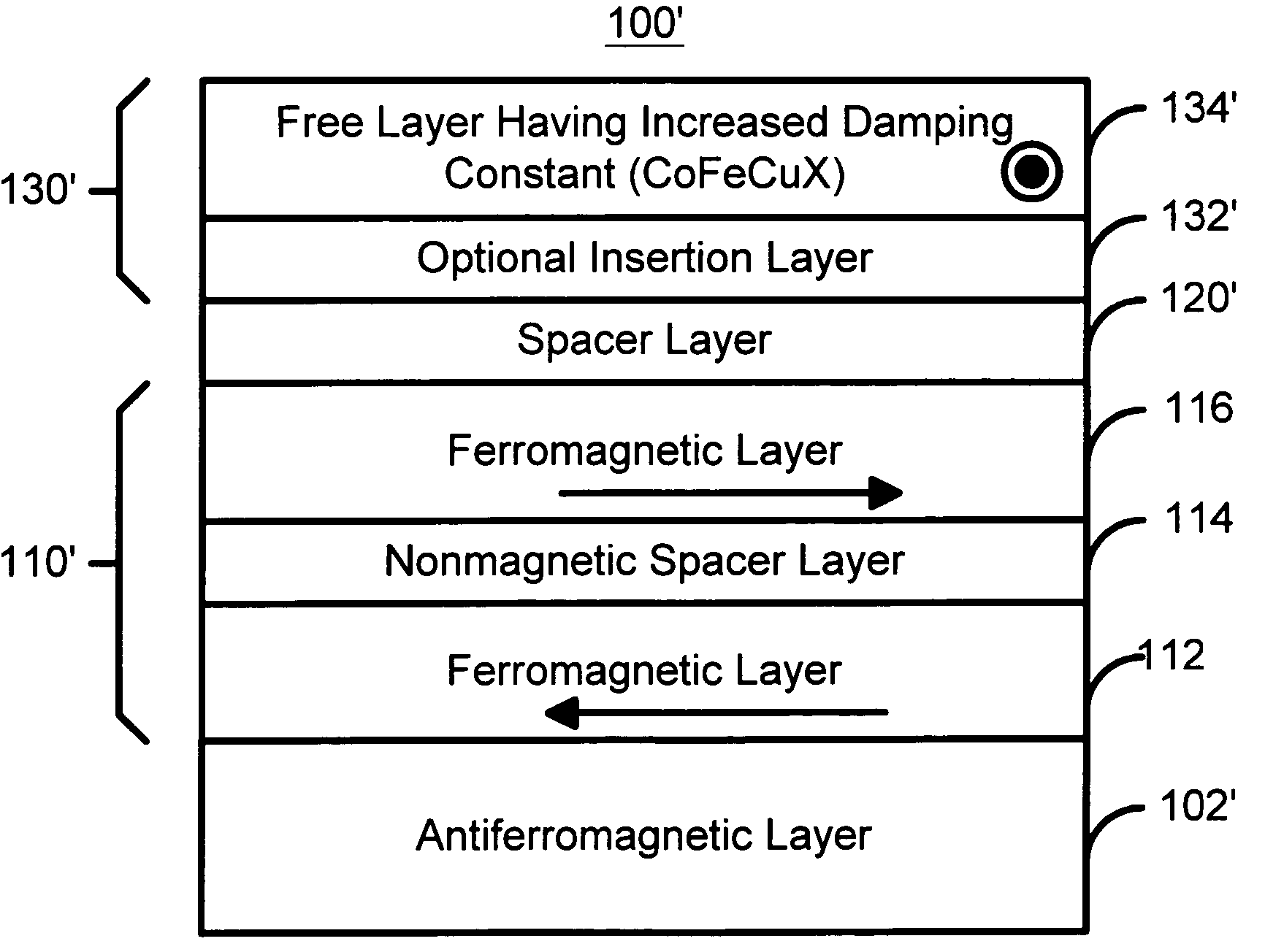
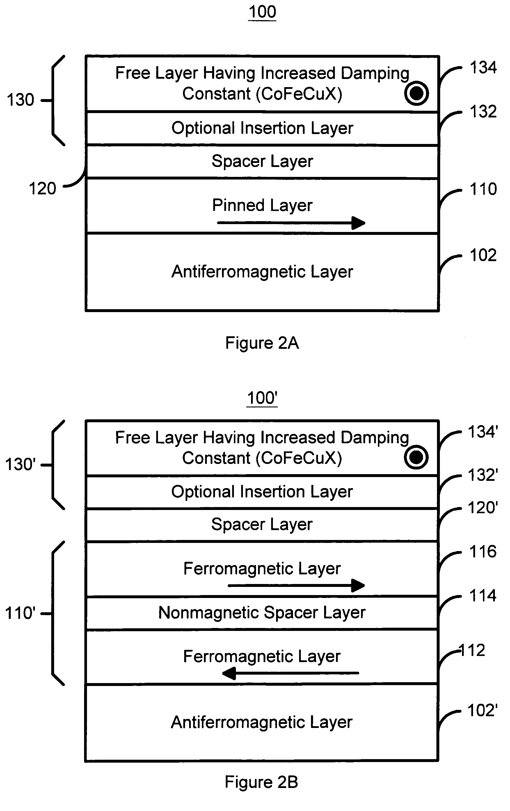
[0030]To more particularly illustrate the method and system in accordance with the present invention, refer now to FIG. 2A, depicting a first version of a magnetic element 100 in accordance with the present invention having reduced noise due to spin transfer. The magnetic element 100 includes a pinned layer 110, a spacer layer 120, and a free layer 130. Also shown is a pinning layer 102, which is generally an AFM layer 102. In a preferred embodiment, the AFM layer 102 is PtMn with a thickness between fifty and five hundred Angstroms. In addition, seed layers (not shown) and capping layers (not shown) may also be provided. The pinned layer 110 is ferromagnetic and may be a simple pinned layer, as shown, or may be a synthetic pinned layer. If simple, the pinned layer 110 may be Co90Fe10 with a thickness of between five and one hundred Angstroms. The spacer layer 120 may be a conducting spacer layer, for example Cu, or an insulating tunneling barrier layer, such as alumina. If the spac...
second embodiment
[0042]FIG. 3 depicts a magnetic element 200 in accordance with the present invention having reduced noise due to spin transfer. The magnetic element 200 is a dual spin valve or dual spin tunneling junction. Thus, portions of the magnetic element 200 are analogous to the magnetic elements 100, 100′, and 100″. The magnetic element 200 includes a first pinned layer 210, a first spacer layer 220, a free layer 230, a second spacer layer 240, and a second pinned layer 250. Also shown are pinning layers 202 and 204, which are generally AFM layers 202 and 204, respectively. In a preferred embodiment, the AFM layers 202 and 204 are PtMn with a thickness between fifty and five hundred Angstroms. In addition, seed layers (not shown) and capping layers (not shown) may also be provided. The spacer layers 220 and 240 may be a conducting spacer layer, for example Cu, or an insulating tunneling barrier layer, such as alumina. If the spacer layers 220 and / or 240 are Cu, the spacer layers 220 and / or ...
third embodiment
[0046]FIG. 4A depicts a first version of a magnetic element 300 in accordance with the present invention having reduced noise due to spin transfer. The magnetic element 300 is a dual spin valve or dual spin tunneling junction. Thus, portions of the magnetic element 300 are analogous to the magnetic elements 100, 100′, 100″, and 200. The magnetic element 300 includes a first pinned layer 310, a first spacer layer 320, a free layer 330, a second spacer layer 340, and a second pinned layer 350. Also shown are pinning layers 302 and 304, which are generally AFM layers 302 and 304, respectively. In a preferred embodiment, the AFM layers 302 and 304 are PtMn with a thickness between fifty and five hundred Angstroms. In addition, seed layers (not shown) and capping layers (not shown) may also be provided.
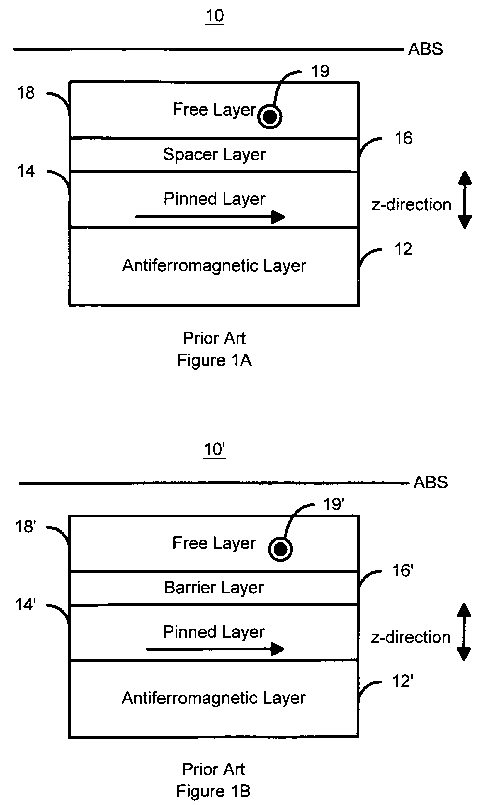
[0047]The magnetic element 300 functions in a similar manner to conventional magnetic elements, such as the conventional magnetic elements 10 and 10′ depicted in FIGS. 1A and 1B, respectiv...
PUM
| Property | Measurement | Unit |
|---|---|---|
| sizes | aaaaa | aaaaa |
| thickness | aaaaa | aaaaa |
| thickness | aaaaa | aaaaa |
Abstract
Description
Claims
Application Information