Compaction monitoring system

a monitoring system and compacting technology, applied in the field of compacting monitoring system, can solve the problems of exacerbated problems, deformation of compactable sediments (or tectonically active areas), and catastrophic loss of producing zones up to and including the loss of a whole well

Active Publication Date: 2007-07-17
SHELL USA INC
View PDF31 Cites 71 Cited by
  • Summary
  • Abstract
  • Description
  • Claims
  • Application Information

AI Technical Summary

Benefits of technology

[0018]In another embodiment, the present invention provides a method of determining a preferred application of a plurality of transducers to a cylindrical structure for monitoring deformation of the structure by: 1) selecting a preferred wrap angle; 2) determining a strain factor for at least one wrap angle within the preferred wrap angle range; 3) determining a preferred wrap angle within the preferred wrap angle range based upon at least one determined strain factor; and 4) determining the preferred application of the plurality of transducers to the structure based on the preferred wrap angle.
[0014]A preferred application of an FBG system, based on a preferred wrap angle, however, has not been proposed. Based on the wrap angle, the application of a FBG system or other conventional sensors to a tubular structure may be uniquely tailored to detect and measure various types and levels of strain the tubular structure is likely to encounter in a particular environment. Thus, strain on the tubular structure may be more accurately detected, in-situ, and measured in real time. As a result, deformation of the tubular structure may be anticipated, if not avoided.

Problems solved by technology

Wells in compactable sediments (or tectonically active areas) are subject to deformation over the productive life of the field.
The result is the catastrophic loss of producing zones up to and including the loss of a whole well.
The problem is exacerbated by the increasingly rapid off-take rates and the completion of multiple zones in a single well.
As the compaction continues, the movement results in a significant misalignment of the well axis.
The result can be the complete loss of the well investment resulting in deferred and / or lost production, if not the replacement cost of a well, which is extremely expensive.
Detection of deformation forces, in-situ, can become a complex problem, particularly when such forces include axial, hoop and shear stresses.
Because the well is shut in, there is a risk that the tool might not come back out.
Such deformations could easily break fibers or elements that are constrained to the tubular structure or casing and caused to strain therewith.
Although several papers have reported on field use of a variety of fiber optic sensors, most have not found wide use in practice, other than for alarm mode or tactile sensing, due to problems associated with erratic response, tolerances of the deformers, mechanical fatiguing of the fiber, and a limited quantitative understanding of the mode problems and radiation loss associated with the use of multimode fiber.
The foregoing optical fiber examples that utilize a bent optical fiber, however, lack a signal-to-noise ratio and dynamic range measurement that is acceptable for monitoring compaction-induced strain on a tubular structure such as casing.
In other words, light lost at each bend adds up quickly and results in a signal that is too low to practically measure.
Conventional FBG systems applied axially or radially to a structure may not, however, be suitable for monitoring compaction induced strain on the structure because fibers or elements that are constrained to the structure and stretched or compressed may break under strain greater than about one to two percent.

Method used


Image

  • Compaction monitoring system
  • Compaction monitoring system
  • Compaction monitoring system

Examples


example 1

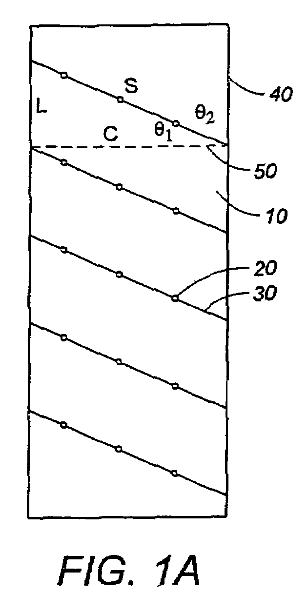
[0101]FIG. 6, illustrates the resulting wavelength response, relative to each numbered transducer, from a cylindrical structure undergoing offset shear in a controlled test. The cylindrical structure is three (3) inches in diameter and twenty-four (24) inches long. Although the transducer spacing along the optical fiber in this test is about 1 centimeter, a spacing of 2 centimeters may be adequate to measure the same shear response in a cylindrical structure with the same diameter. A preferred wrap angle of about 20 degrees was used. The detectable variation in wavelength response, representing lateral offset, was between 0.001 inches up to about 0.600 inches.

[0102]In this example, a 0.001-inch lateral offset translates into a dogleg in the structure of about less than one-half degree for each one hundred-foot section of the structure, which is inconsequential. However, a lateral offset of about 0.1 inch over the same length of structure translates into a dogleg of approximately 48 ...

example 2

[0107]In this example, accurate measurements of low strain and high sensitivity to bending or buckling induced by axial compaction are important objectives. A thin-walled PVC pipe was tested using the weight of the pipe, horizontally suspended by its ends, as the applied force. A preferred wrap angle of about 20 degrees was used to apply the transducers and optical fiber to a 10-foot long section of the pipe with a 6.5-inch diameter. A 5-centimeter transducer spacing was used to resolve the wavelength response from a buckle or a bend.

[0108]In FIG. 8, the wavelength response resulting from the lateral force applied by the weight of the pipe is illustrated. A maximum lateral offset of about 0.07 inches was detected. The wavelength response in FIG. 8 clearly reveals a bend or a buckle because one period or cycle of the wavelength response corresponds to one wrap of the fiber. A 0.07-inch lateral offset represents less than a 7-degree bend or buckle for each one hundred-foot section of ...

example 3

[0109]In this example, the same pipe was tested using a weight hung from the center of the pipe, which was horizontally suspended at each end. The lateral offset due to a bend is about 0.228 inches. As illustrated in FIG. 9, a relatively clean periodic signal is apparent everywhere except at the ends and at the center of the wavelength response where the weight is hanging and distorting the signal. The distorted signals are a special case related to pipe crushing caused by local loading on the pipe.

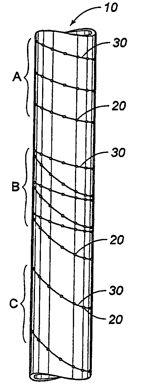
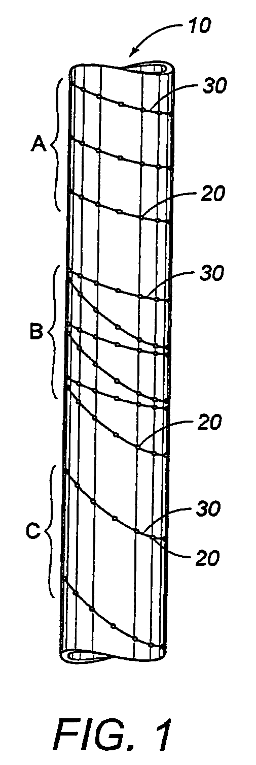
[0110]FIG. 10 represents a simple illustration of a lateral force on the structure 10 induced by axial compaction. Here the structure 10 is subjected to a lateral force 310 on one side of the structure 10. The wavelength response, representing strain on the structure 10 measured by transducers 20, associated with the lateral force 310 is periodic and approximately sinusoidal as illustrated in FIG. 10A. The period of the wavelength response or signal is equal to about one cycle per wrap of...


PUM


Abstract

Methods for determining a preferred application of a plurality of transducers or sensors to a structure are disclosed for monitoring and imaging deformation of the structure as it is subjected to various forces.

Description

FIELD OF INVENTION[0001]The present invention generally relates to methods for determining a preferred application of a plurality of transducers or sensors to a cylindrical structure for monitoring deformation of the structure as the structure is subjected to various forces. The present invention is also directed to methods for imaging deformation of an object as the object is subjected to various forces.BACKROUND OF THE INVENTION[0002]Wells in compactable sediments (or tectonically active areas) are subject to deformation over the productive life of the field. The result is the catastrophic loss of producing zones up to and including the loss of a whole well. The problem is exacerbated by the increasingly rapid off-take rates and the completion of multiple zones in a single well. The observable phenomenon is that at first a well casing will bend or begin to buckle, frequently at casing joints, or interfaces in the formation. As the compaction continues, the movement results in a si...

Claims


Application Information

Patent Timeline
Patent Type & Authority Patents(United States)
IPC IPC(8): G02B6/00G02B6/34
CPCE21B47/0006G01B11/165E21B47/123E21B47/007E21B47/135G01B11/18
Inventor RAMBOW, FREDERICK HENRY KREISLERDRIA, DENNIS EDWARDSHUCK, MICHELLE YVONNE
Owner SHELL USA INC
Why Eureka
Try Eureka