Architecture for dynamic connectivity in an edge photonic network architecture

a photonic network and network architecture technology, applied in the field of aggregation of groups of tunable sources in a photonic network, can solve the problems of lack of scalability, large size of oeo switches, high power consumption, etc., and achieve the effect of ready optical connectivity

Active Publication Date: 2007-07-17
RPX CLEARINGHOUSE
View PDF4 Cites 85 Cited by
  • Summary
  • Abstract
  • Description
  • Claims
  • Application Information

AI Technical Summary

Problems solved by technology

These factors cause OEO switches to be large in size, to have high power consumption in the range of kilowatts, to be network protocol and transmission rate dependent, to lack scalability, and to be costly.
All-optical networks encounter issues of aggregating and disaggregating communication channels.
Power combiners may be used to aggregate channels, but have the inherent problem of introducing high loss as channels are aggregated.
Overcoming losses with all-optical amplifiers introduces noise.

Method used


Image

  • Architecture for dynamic connectivity in an edge photonic network architecture
  • Architecture for dynamic connectivity in an edge photonic network architecture
  • Architecture for dynamic connectivity in an edge photonic network architecture

Examples


Embodiment Construction

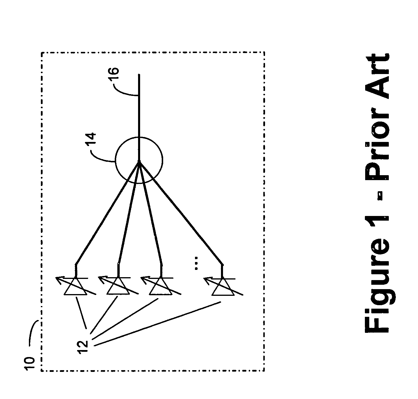
[0026]Referring to FIG. 1, there is illustrated a transmit cluster 10 having a means of combining optical signal channels as is known in the art. Transmit cluster 10 has a plurality of tunable wavelength optical transmitters 12. These typically may be lasers with associated optical modulators. The outputs of the transmitters 12 are optically connected (note: for the purposes of this specification an optical connection means an optical pathway between devices is established according to means well known in the art including such interconnecting devices as necessary to appropriate optical signal transfer, examples of which include optical fiber, connectors, amplifiers, attenuators, dispersion compensators, and the like) to the inputs of optical power combiner 14. The output 16 of optical power combiner 14 provides an aggregated set of optical channels, however has difficulty scaling to larger numbers of optical transmitters.

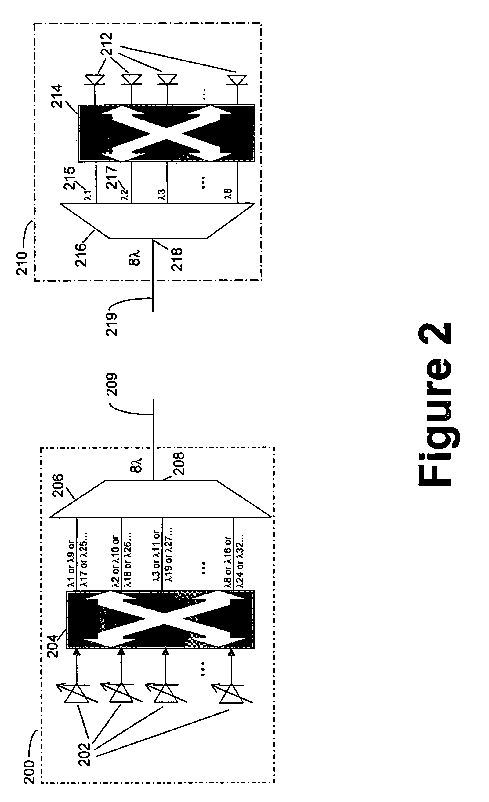
[0027]Referring to FIG. 2, there is illustrated a transmit ed...


PUM


Abstract

A network arrangement for aggregation of groups of tunable sources in a photonic network is disclosed. The network arrangement includes transmit edge elements having a plurality of tunable optical transmitters, an optical switch and a cyclic optical multiplexer, and receive edge elements having optical demultiplexers, optical switches and a plurality of optical receivers. A variety of arrangements are disclosed including protected and unprotected network architectures. The network arrangement disclosed is particularly useful for overcoming the problem of scaling a photonic network.

Description

FIELD OF THE INVENTION[0001]The present invention relates to aggregation of groups of tunable sources in a photonic network and is particularly concerned with provision of optical network connections between elements in a photonic network without the use of optical-to-electrical-to-optical conversion.BACKGROUND OF THE INVENTION[0002]Presently existing optical networks include optical-to-electrical-to-optical (OEO) conversion at many points. A typical wavelength switch used today converts the input light signal into an electronic signal to detect the routing information, switches the electronic signal, and then eventually reconverts it back into a light signal for further transmission. This device, commonly referred to as an Optical-Electrical-Optical (OEO) switch, not only depends on current semiconductor technologies and processes, but also requires a transmitter and a receiver for each transmission port. These factors cause OEO switches to be large in size, to have high power cons...

Claims


Application Information

Patent Timeline
Patent Type & Authority Patents(United States)
IPC IPC(8): H04J14/00H04J14/02
CPCH04J14/0227H04J14/029H04J14/0297H04Q11/0005H04J14/0246H04J14/025H04J14/0282H04Q11/0071H04Q2011/0015H04Q2011/0016H04Q2011/0032
Inventor SINDILE, PIA
Owner RPX CLEARINGHOUSE
Why Eureka
Try Eureka