Sensor malfunction detection system for gas-turbine engine

a technology of malfunction detection and gas turbine engine, which is applied in the direction of machines/engines, process and machine control, mechanical roughness/irregularity measurement, etc., can solve the problems of complicated techniques and achieve the effect of simple configuration and good accuracy

Active Publication Date: 2007-07-17
HONDA MOTOR CO LTD
View PDF13 Cites 33 Cited by
  • Summary
  • Abstract
  • Description
  • Claims
  • Application Information

AI Technical Summary

Benefits of technology

[0008]An object of this invention is therefore to overcome the aforesaid problem and to provide a sensor malfunction detection system for a gas-turbine engine that can detect sensor malfunction with good accuracy using a simple configuration.

Problems solved by technology

Thus, both techniques are complicated.

Method used


Image

  • Sensor malfunction detection system for gas-turbine engine
  • Sensor malfunction detection system for gas-turbine engine
  • Sensor malfunction detection system for gas-turbine engine

Examples


Embodiment Construction

[0022]Sensor malfunction detection system for a gas-turbine engine according to preferred embodiment of this invention will now be explained with reference to the drawings.

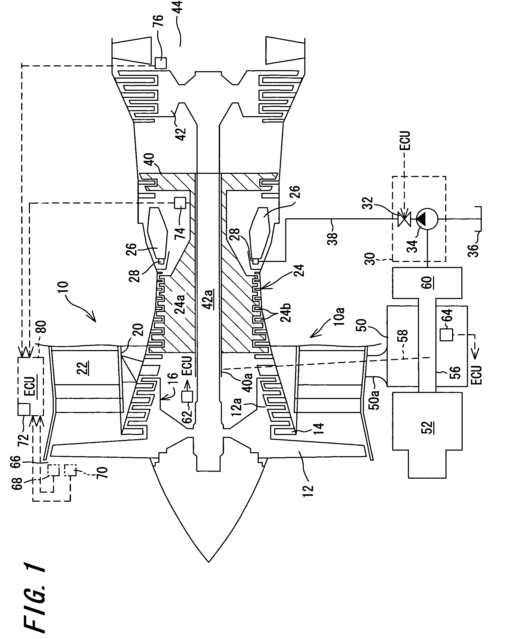
[0023]FIG. 1 is an overall schematic view of a gas-turbine engine control unit capable of utilizing a sensor malfunction detection system according to an embodiment of this invention.

[0024]The sensor malfunction detection system according to this invention is a system for detecting malfunction that is used in the gas-turbine engine control unit. Therefore, in order to facilitate understanding of ensuing explanation of the sensor malfunction detection system, the gas-turbine engine control unit will be explained first.

[0025]The explanation will be made taking a gas-turbine aeroengine for aircraft as an example of the gas-turbine engine. Four types of gas-turbine aeroengines are commonly used in aircraft: the turbojet engine, turbofan engine, turboprop engine and turboshaft engine. A two-spool (shaft) turbofan engin...


PUM


Abstract

The sensor malfunction detection system for a gas-turbine engine is configured to determine or check once every first predetermined time period whether the outputted value from the sensor is within a permissible range and determines that the sensor is faulty when the result of the check is at least one result between the case of the number of times the outputted value is found not to be within the permissible range exceeding a first predetermined value and the case of the number of times the outputted value is consecutively found not to be within the permissible range exceeding a second predetermined value. Since the system discriminates whether the total number of times the sensor output is found to be outside the permissible range is fewer than the first predetermined value, it can avoid erroneous detection of transient abnormalities caused by noise or the like as sensor malfunction, and since it discriminates whether the number of times the sensor output is consecutively found not to be within the permissible range is fewer than the second predetermined value, it can promptly detect sensor malfunction owing to wire breakage or the like. The system can therefore detect sensor malfunction with good accuracy using a simple configuration.

Description

BACKGROUND OF THE INVENTION[0001]1. Field of the Invention[0002]This invention relates to a sensor malfunction detection system for a gas-turbine engine, more specifically a sensor malfunction detection system for a gas-turbine aeroengine used in aircraft.[0003]2. Description of the Related Art[0004]Gas-turbine engine control is performed by using the outputs of a group of sensors installed in the engine to discriminate the engine operating condition and conducting various kinds of control, including calculation and control of the amount of fuel to be supplied, based on the discriminated condition. If a sensor should fail because of wire breakage or the like, its output will deviate from the right value. This makes it necessary to detect whether any of the sensors are faulty.[0005]Japanese Laid-open Patent Application No. Sho 61(1986)-241424 teaches a technique for selecting the best value among two sampled values of a sensor output and composite signals representing nominal values ...

Claims


Application Information

Patent Timeline
Patent Type & Authority Patents(United States)
IPC IPC(8): G01C25/00G01M17/00G01M15/14F01D17/02F01D25/00F02C7/00F02C9/00F02C9/28G01M15/00G01M99/00G05B9/02G06F15/00
CPCF01D17/02F02C9/00G05B9/02G01M15/00
Inventor MURAMATSU, HIRONORISUGITANI, YUKINOBU
Owner HONDA MOTOR CO LTD
Why Eureka
Try Eureka