
Method for controlling a drivetrain in a motor vehicle

a technology for driving gears and motor vehicles, applied in mechanical equipment, transportation and packaging, gearboxes, etc., can solve the problems of large structural space, high manufacturing cost, and large components of range transfer boxes constructed with separate mechanical synchronization means or frictional shift elements, etc., to achieve less structural space, high torque, and simple design

Inactive Publication Date: 2007-07-24
ZF FRIEDRICHSHAFEN AG
View PDF16 Cites 0 Cited by
  • Summary
  • Abstract
  • Description
  • Claims
  • Application Information

AI Technical Summary

Benefits of technology

[0011]When a transmission ratio of the range transfer box is changed, synchronization of a shift element of the range transfer box to be engaged is carried out by the control of shift elements of the automatic transmission; in an advantageous way, there is no longer any need for mechanical synchronization means to be provided in the range transfer box itself—whether as separate components or integrated in shift elements of the range transfer box. This makes it possible to construct a range transfer box which is of considerably simpler design compared with the multi-range transmissions known from the prior art, such that the range transfer box takes up less structural space.
[0013]In addition, it is advantageous that the omission of mechanical synchronization means in the range transfer box reduces drag torques of opened mechanical synchronization means and the evolution of heat in the range transfer box is substantially reduced. Drag torques occur in mechanical synchronization systems essentially because of the fluid friction that takes place between the friction linings of frictional clutches or brakes, caused by oil.

Problems solved by technology

This has the disadvantage, however, that range transfer boxes constructed with separate mechanical synchronization means or with frictional shift elements comprise large components and take up a lot of structural space, since they have to be made appropriately robust because of the high stressing of the components during synchronization.
Furthermore, separate mechanical synchronization means or frictional shift elements incur high manufacturing costs, and this is uneconomical.

Method used


Image

  • Method for controlling a drivetrain in a motor vehicle
  • Method for controlling a drivetrain in a motor vehicle
  • Method for controlling a drivetrain in a motor vehicle

Examples


Embodiment Construction

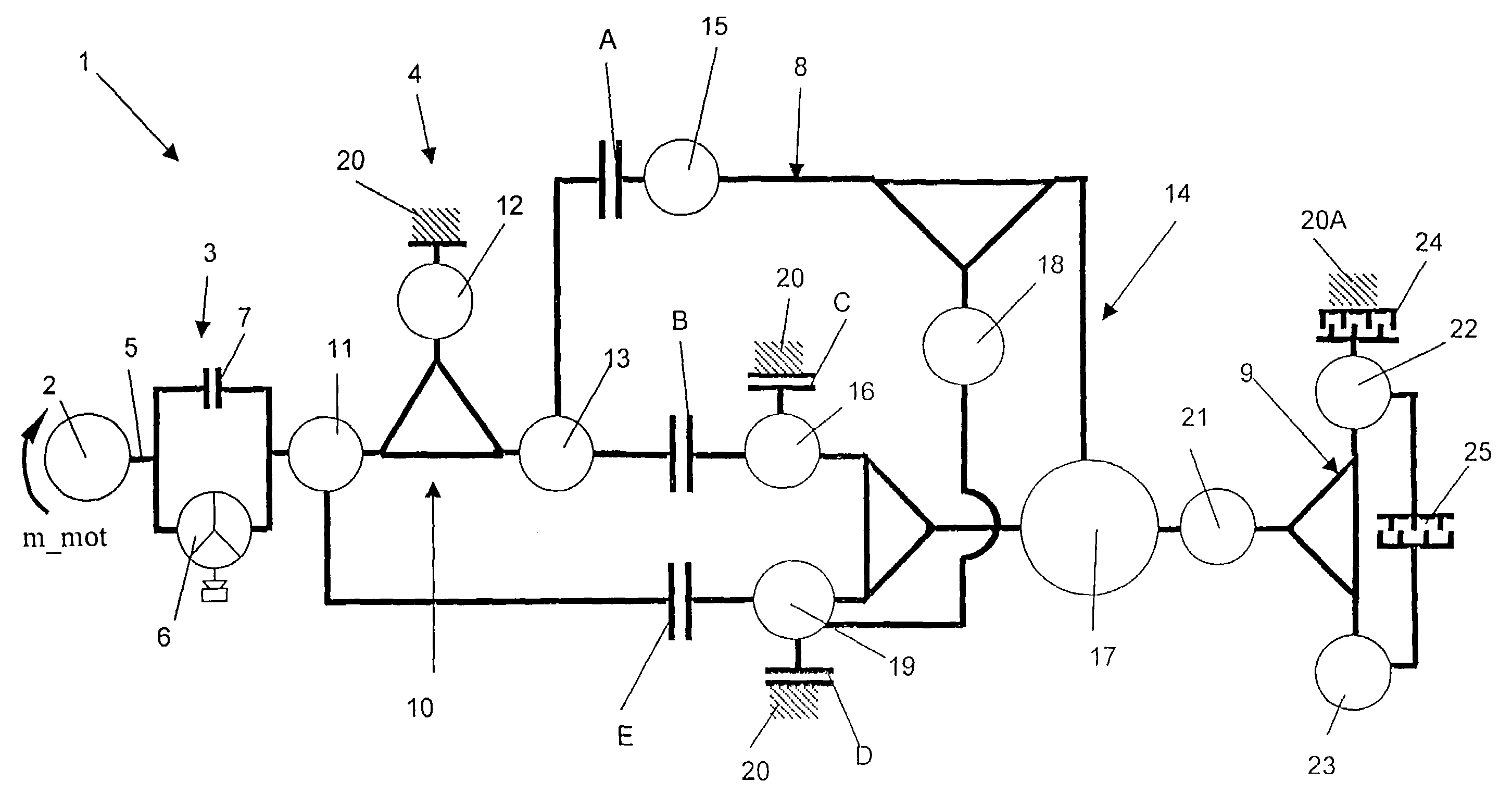
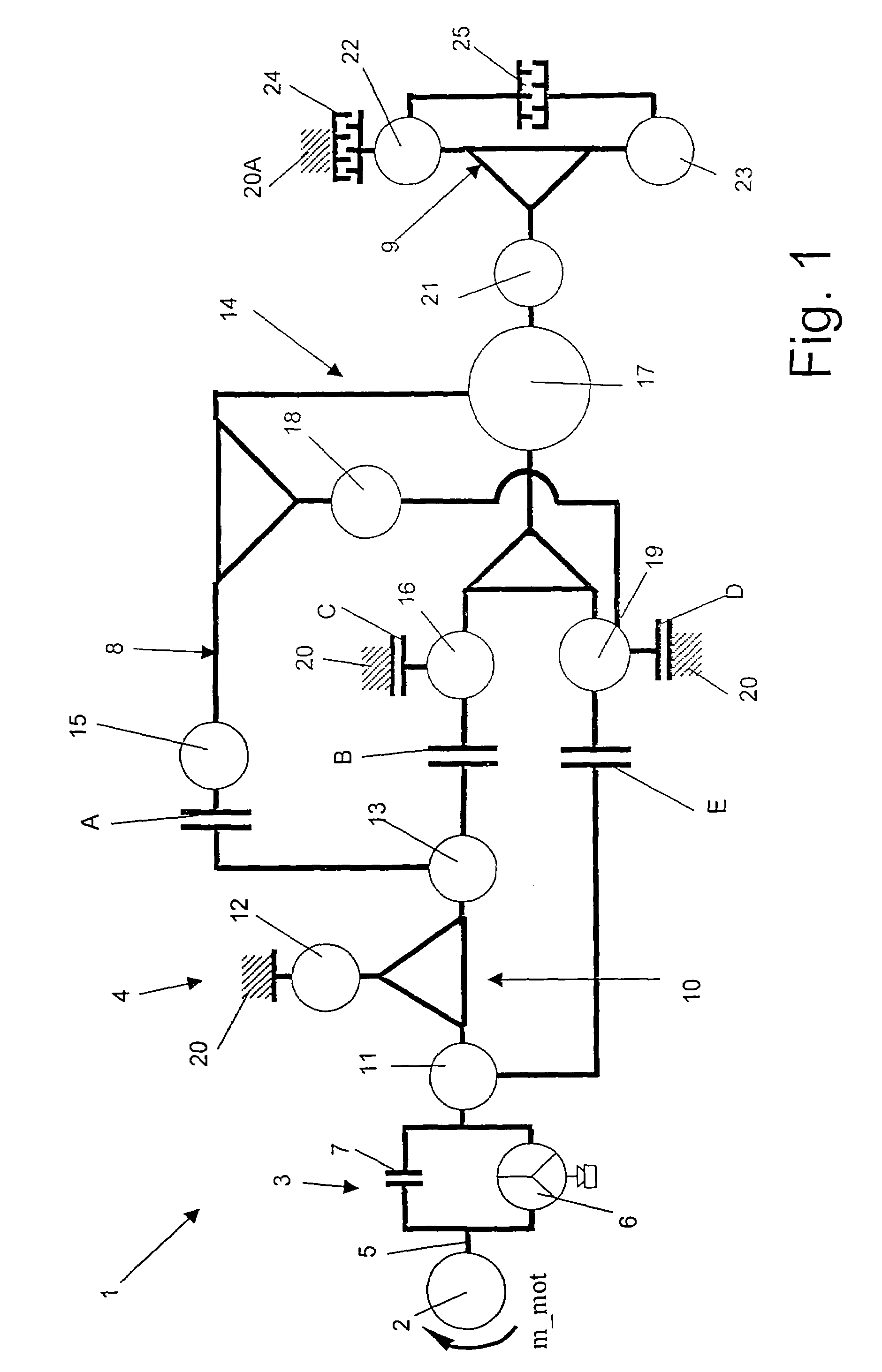
[0027]Referring to FIG. 1, a drivetrain 1 of a vehicle (of which no more is shown), in particular an off-road vehicle, is represented very schematically. In this case, the drivetrain 1 consists of a drive engine 2, a starting element 3 and a multi-range transmission 4. The drive engine 2 is an internal combustion engine whose drive torque m_mot is transferred via an output shaft 5 to the starting element 3 made with a hydrodynamic torque converter 6. In addition, the starting element 3 is formed with a converter clutch 7, with which the hydrodynamic torque converter can be bypassed.

[0028]The multi-range transmission 4 connected in series downstream from the starting element 3 is, in this case, formed by an automatic transmission 8 and a downstream range transfer box 9; the automatic transmission 8 constituting the main gear system of the multi-range transmission 4.

[0029]This gear combination of the present multi-range transmission 4 consists of the change-under-load automatic transm...


PUM


Abstract

A method for controlling a drivetrain (1) in a motor vehicle is disclosed, in particular in an off-road vehicle with a drive unit (2), a multi-group transmission (4) and an output. The multi-group transmission (4) comprises at least an automatic gearbox (8) and a subsequent range transfer box (9) which may be switched by means of switching elements (24, 25). On changing the ratio in the range transfer box (9), a synchronisation of the switching element (24 or 25), for switching in the range transfer box (9), is carried out by means of a controller of switching elements in the automatic gearbox (8).

Description

[0001]This application is a national stage completion of PCT / EP2003 / 009104 filed Aug. 18. 2003 which claims priority from German Application Serial No. 102 38 127.5 filed Aug. 21. 2002.FIELD OF THE INVENTION[0002]The invention concerns a method for controlling the drivetrain in a vehicle.BACKGROUND OF THE INVENTION[0003]From prior practice drivetrains of vehicles, in particular off-road vehicles, are known, which comprise a drive engine, a multi-range transmission and a drive output. The incorporation of a multi-range transmission enables several gear speeds to be made available with the fewest possible gear wheel pairings.[0004]In practice, a multi-range transmission consists of a combination of several transmission units, such as a so-termed upstream reduction gear group, a main transmission and a downstream group or range transfer box. To provide good shifting comfort and as many speed shifts as possible, the main transmission is preferably made as an automatic transmission, for ...

Claims


Application Information

Patent Timeline
IPC IPC(8): F16H31/00F16H61/686F16H61/70F16H61/04
CPCF16H61/702F16H2300/18Y10T477/675F16H2306/48F16H2306/42
Inventor PELCHEN, CHRISTOPHBAASCH, DETLEFSCHMOHL, BARBARAGAZYAKAN, UNAL
Owner ZF FRIEDRICHSHAFEN AG
Learn More