Voltage-activated, constant current sink circuit

a constant current sinking and voltage-activated technology, applied in the field of constant current sinking circuits, can solve the problems of high cost components, more centralized, expensive, and high-cost components used in the system, and achieve accurate sinking current and cost reduction

Inactive Publication Date: 2007-07-24
MICREL
View PDF6 Cites 33 Cited by
  • Summary
  • Abstract
  • Description
  • Claims
  • Application Information

AI Technical Summary

Benefits of technology

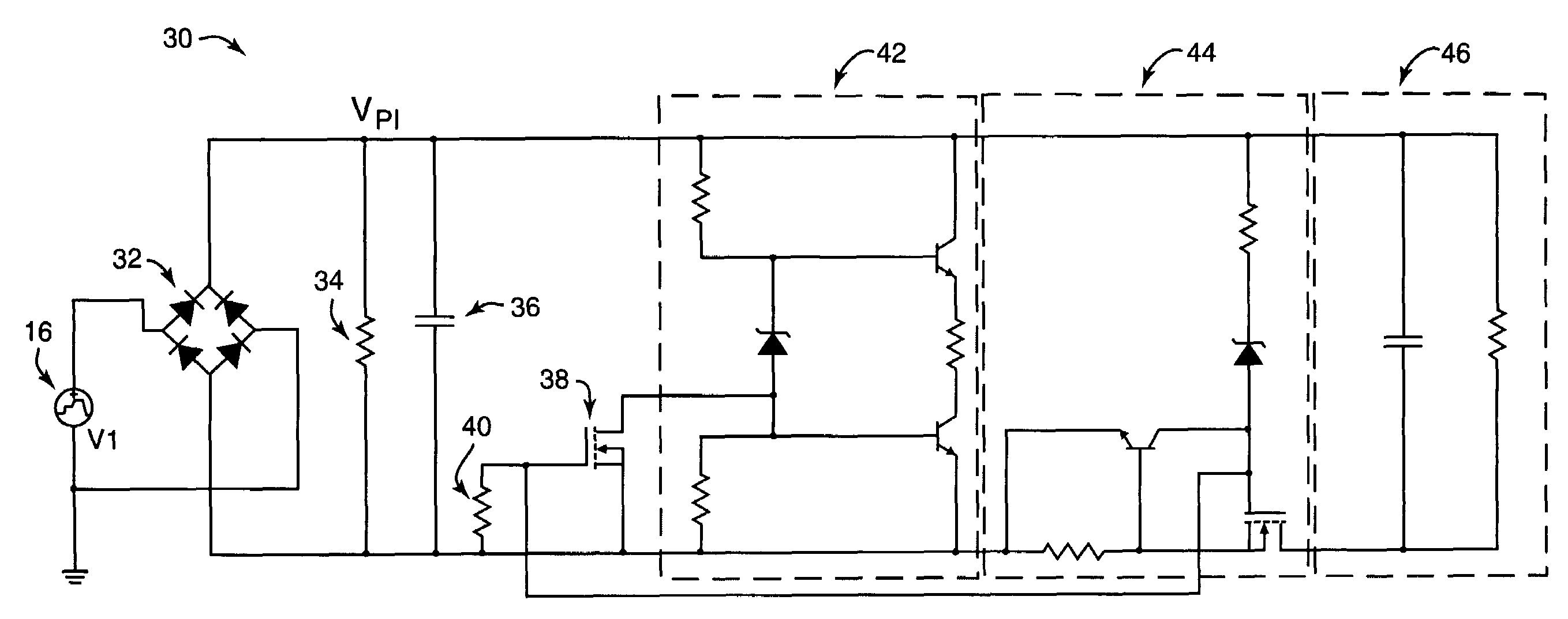
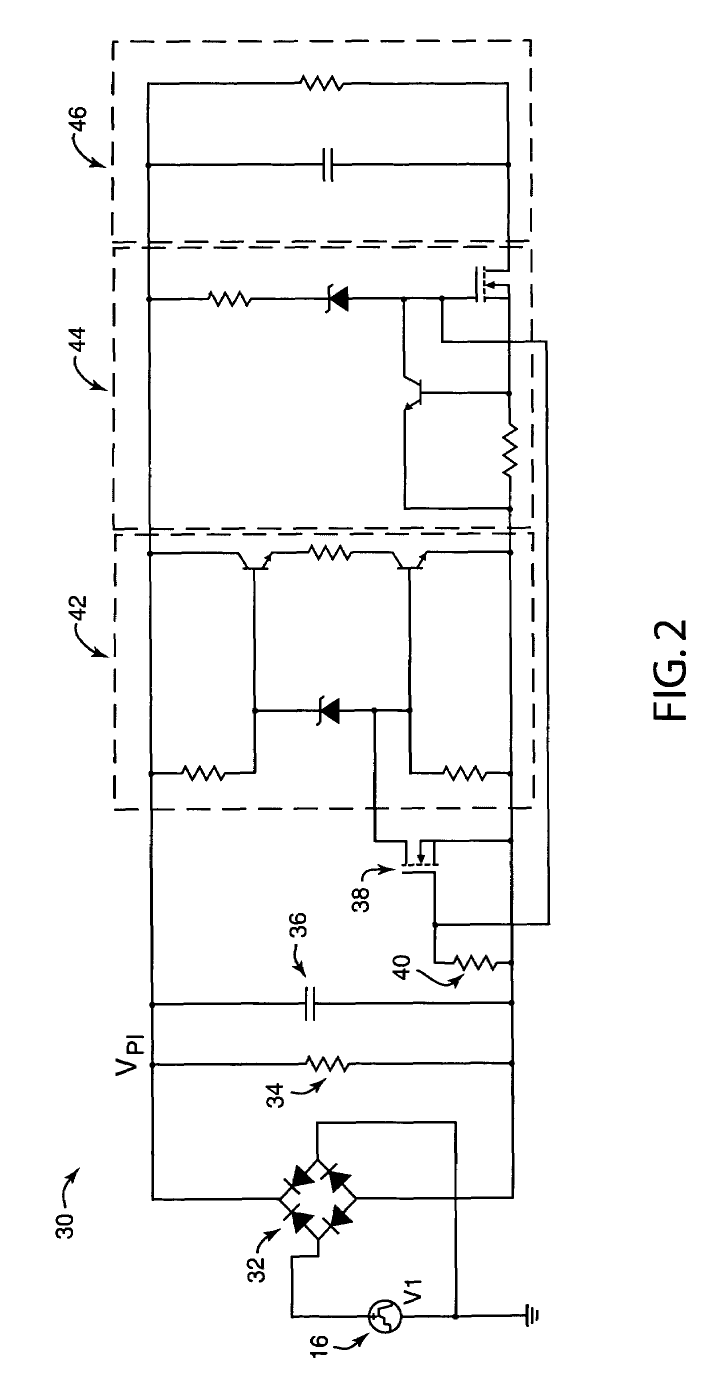
[0010]In another aspect of the present invention, a method for accurately sinking current includes preventing current received from a power source from flowing through a resistor when an input voltage is below a predetermined voltage level, where the predetermined voltage level is determined by the voltage rating of the zener diode. A constant current flow is allowed through the resistor above the predetermined voltage level by switching on a transistor at a voltage above the voltage rating of the zener diode.
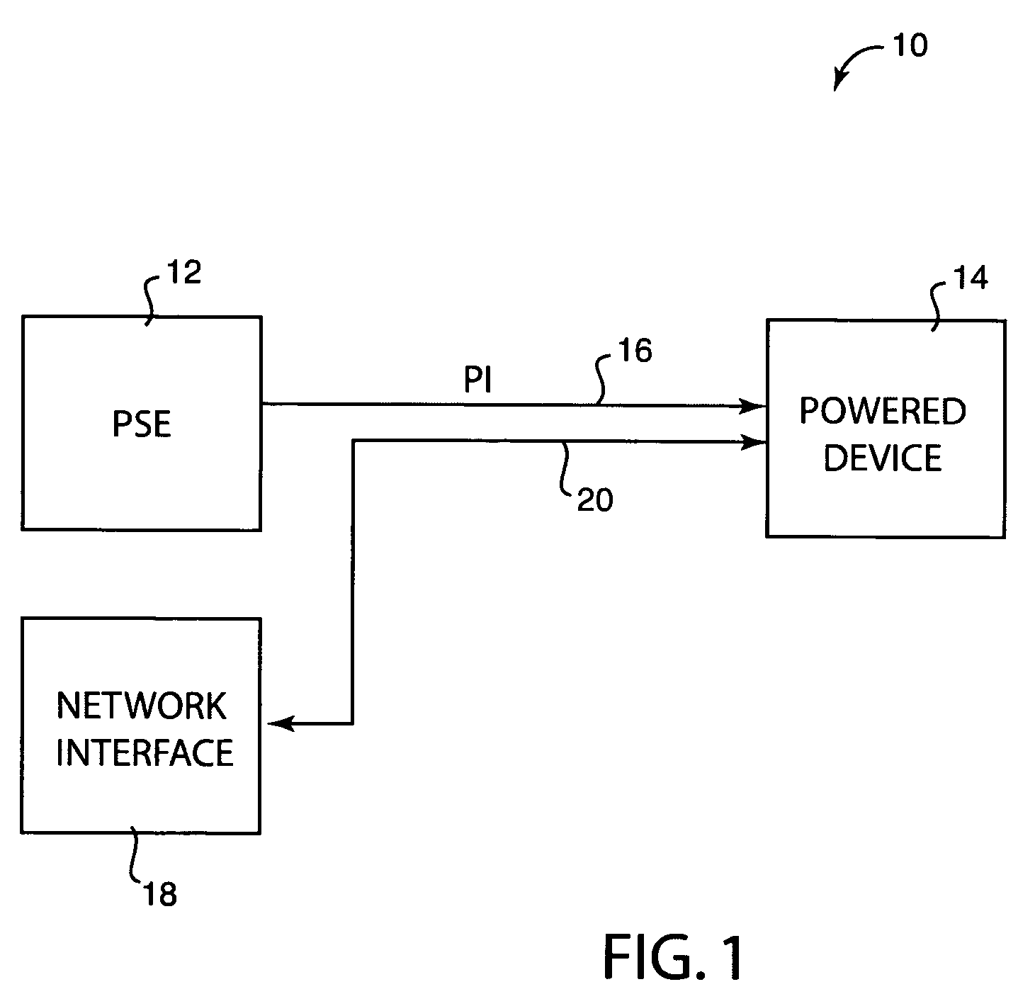
[0011]The present invention provides low-cost, discrete components to be used in a current sink and regulation circuit. The invention provides an accurate current sink that is voltage activated at a predetermined voltage and allows necessary analog handshaking under a desired standard. The present invention allows a device using the circuit, such as a powered device under the Power over Ethernet standard, to avoid the use of expensive components such as operational amplifiers and high voltage level shifters, and therefore be much reduced in costs. Further low-cost circuits of the present invention are provided for isolating a load and for current limiting.

Problems solved by technology

This helps to minimize the cost of these typically cost-sensitive devices so that the major burden of power control and device detection is put on the PSE, which is typically the more centralized, integrated and expensive part of the system.
However, one problem with currently-used PoE circuitry used in powered devices is that high-cost components are commonly used.
These types of components significantly increase the cost of the powered device.

Method used


Image

  • Voltage-activated, constant current sink circuit
  • Voltage-activated, constant current sink circuit
  • Voltage-activated, constant current sink circuit

Examples


Embodiment Construction

[0019]The present invention relates to relates generally to current regulation circuits, and more particularly to constant current sink circuits. The following description is presented to enable one of ordinary skill in the art to make and use the invention and is provided in the context of a patent application and its requirements. Various modifications to the preferred embodiment and the generic principles and features described herein will be readily apparent to those skilled in the art. Thus, the present invention is not intended to be limited to the embodiment shown but is to be accorded the widest scope consistent with the principles and features described herein.

[0020]The present invention is mainly described in terms of particular circuits provided in particular implementations. However, one of ordinary skill in the art will readily recognize that this system will operate effectively in other implementations. For example, the circuits described for use with the present inven...


PUM


Abstract

Voltage-activated and accurate current sink, and method of providing same. In one aspect, a circuit for accurately sinking current includes a zener diode coupled to a power source at the cathode of the zener diode, and first and second transistors, where the first transistor has its collector coupled to the power source and its base coupled to the cathode of the zener diode, and the second transistor has its base coupled to the anode of the zener diode and its emitter coupled to ground. A resistor is coupled between the emitter of the first transistor and the collector of the second transistor.

Description

FIELD OF THE INVENTION[0001]The present invention relates generally to current regulation circuits, and more particularly to constant current sink circuits.BACKGROUND OF THE INVENTION[0002]Current sinks and regulators are used in a variety of applications and devices to provide a desired current to a circuit or device accurately and without large fluctuations. Some standards and devices require voltages and currents to be provided at accurate levels or within well-defined ranges, for operation and for detection and identification of characteristics or to determine whether a device is operating within a known standard.[0003]One existing technology that makes use of such voltage and current regulation is Power over Ethernet for networked electronic devices. Electronic devices are often linked together via communication networks that allow the devices to communicate and share data. Local area networks (LANs), wide-area networks (WANs), the Internet, wireless networks, etc., are just so...

Claims


Application Information

Patent Timeline
Patent Type & Authority Patents(United States)
IPC IPC(8): G05F1/10
CPCH02J1/06H02M7/2176
Inventor MONTGOMERY, SEAN
Owner MICREL
Why Eureka
Try Eureka