Method and device for monitoring analyte concentration by optical detection

a technology of optical detection and analyte concentration, applied in the field of biological sensors, can solve the problems of inconvenient patient, difficulty in satisfactory measurement, and need to take blood samples, and achieve the effect of reducing the effect of stray ligh

Inactive Publication Date: 2007-07-24
P&V CONSULTING
View PDF10 Cites 120 Cited by
  • Summary
  • Abstract
  • Description
  • Claims
  • Application Information

AI Technical Summary

Benefits of technology

[0013]The difference between the said distances allows a differential analysis to take place so that the effects of skin in the results can be reduced or avoided. The differential analysis may be a simple formation of a difference in signals or may be a complex computer correlation. The analysis may be performed within the device or externally.
[0020]The areas may be provided within wells to reduce the effects of stray light.
[0021]The areas may be covered by optical filter means to prevent light of wavelengths other than those of interest from reaching the areas.
[0038]Such methods allow non-invasive measurement after the initial implantation in which the influence of bio fouling on the value of the measured signal is decreased.

Problems solved by technology

The disadvantage of these test kits is the need to take a blood sample which must be collected from a suitable place in the body.
Self monitoring devices, based on capillary blood glucose, are practical but still require repeated and frequent skin punctures, which is inconvenient for the patient and require certain hygienic precautions.
Various proposals have been made for non-invasive measurement of glucose levels in the human body by spectroscopic methods but the effects of water in the body, the low concentration of glucose to be measured and the optical effects produced by skin all contribute to the difficulty of making satisfactory measurements.
11 et seq) has been to provide an implanted window in the skin but, leaving aside any other considerations, some patients, at least, would find this unpleasant.
This technique has the disadvantage that the skin has an effect both on the entry and the exit of light.

Method used


Image

  • Method and device for monitoring analyte concentration by optical detection
  • Method and device for monitoring analyte concentration by optical detection
  • Method and device for monitoring analyte concentration by optical detection

Examples


Embodiment Construction

[0055]In the illustrated embodiments of the invention, optical methods based on the interaction of light with compounds and body tissues are utilised. The optical methods in their general aspects correspond to those described in the literature, for example, using Beer-Lambert law and / or radiative transport theory and will not therefore be described further here.

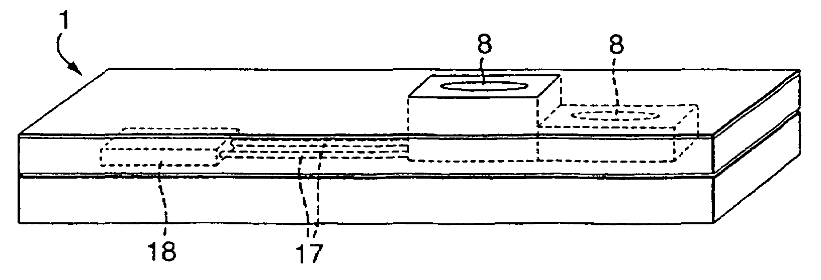
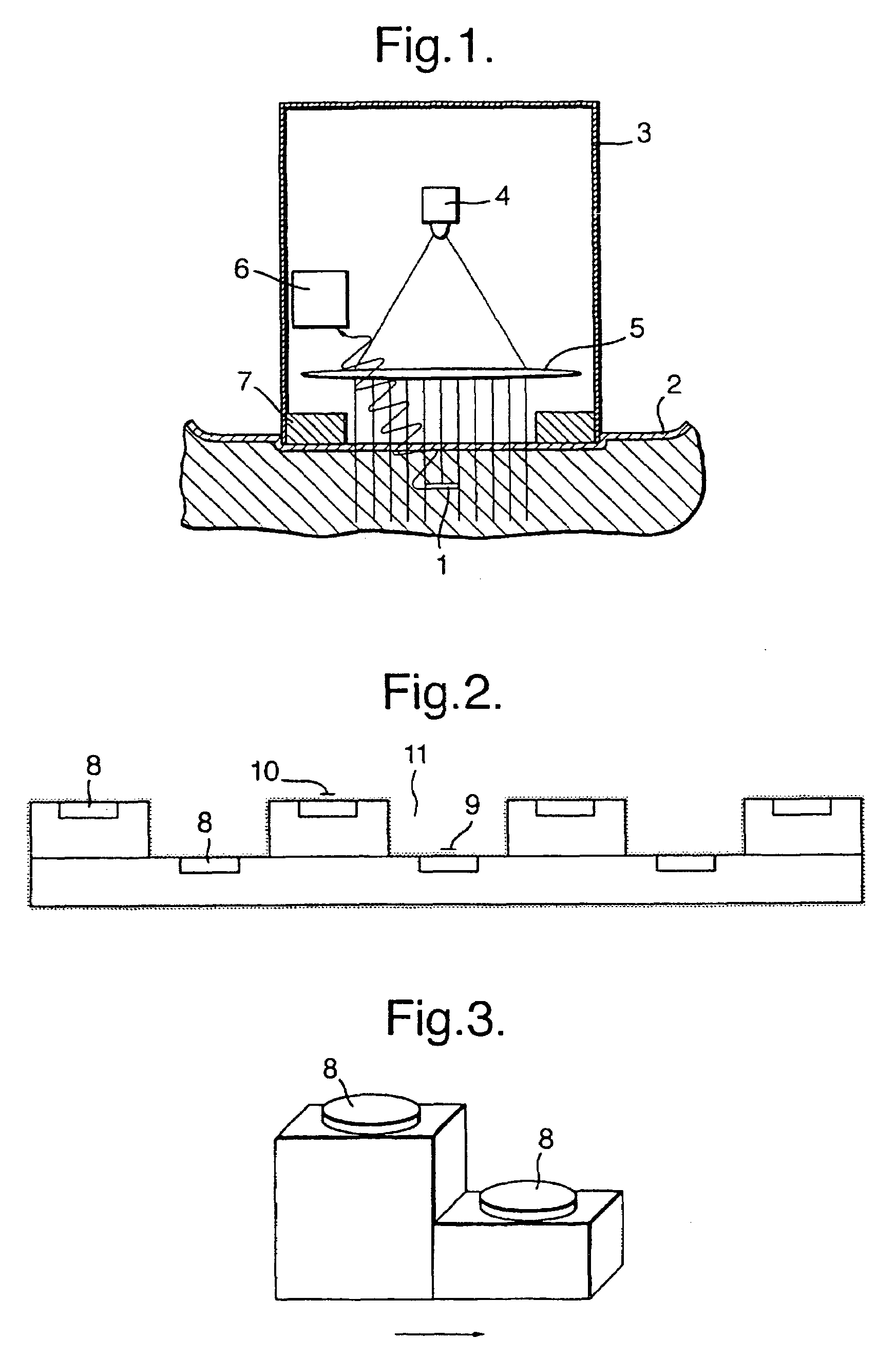
[0056]In the illustrated embodiments of the invention, light from a light source is incident on an implanted detector, the light is detected by a detection device in the implanted detector, and a signal is transmitted to a receiving device for analysis. The characteristics of the detected light depend on the interaction with the compounds encountered on the way from the light source to the detector.

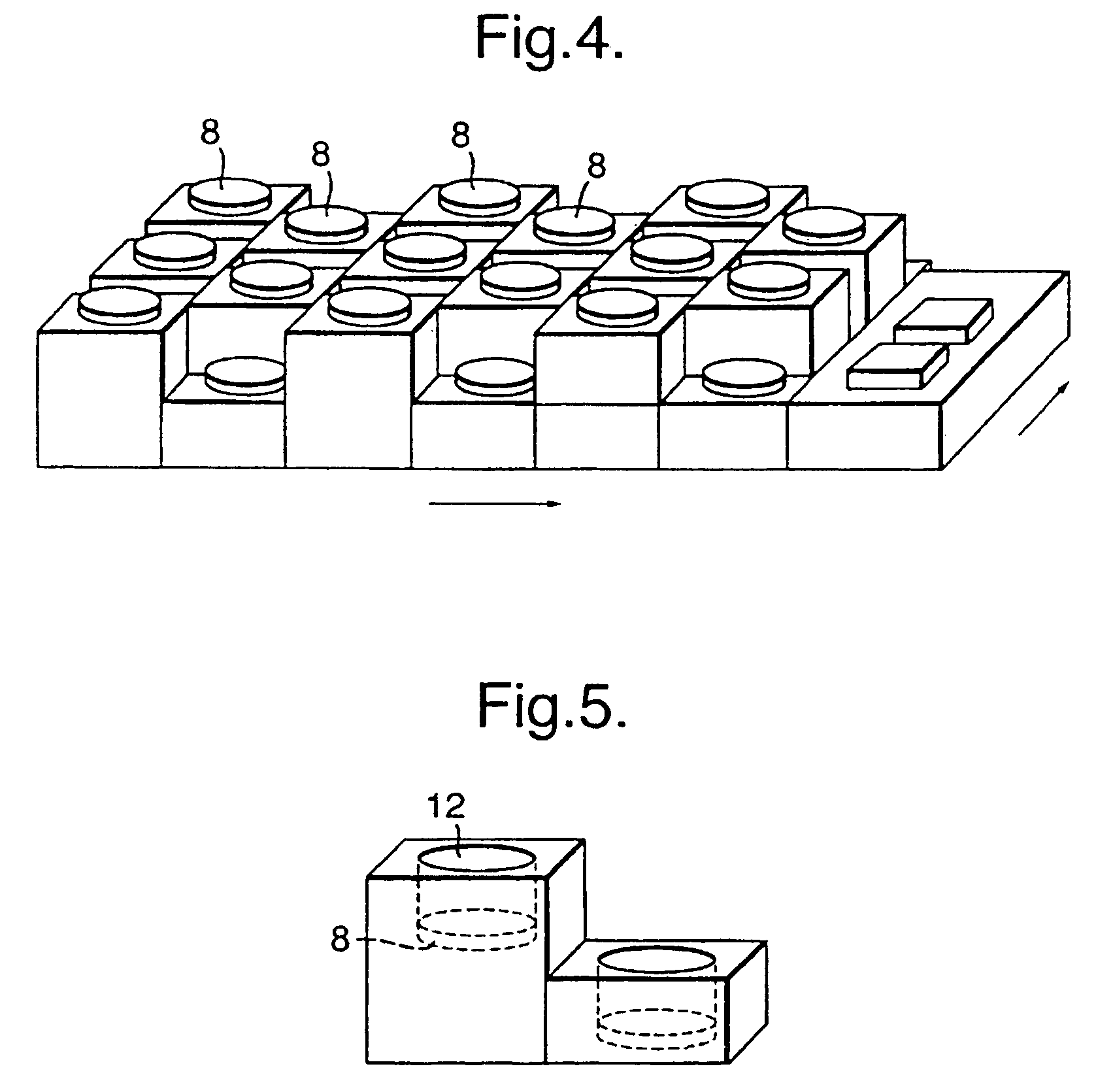
[0057]In the illustrated embodiments of the invention, the implanted detector is divided into areas at different levels, so that the distance for the light through the compounds, and thus the interaction with light, varies from are...


PUM

PropertyMeasurementUnit
biocompatibleaaaaaaaaaa
distanceaaaaaaaaaa
areasaaaaaaaaaa

Abstract

A method and device are provided for the determination of the concentration of compounds in body tissue. The method utilises optical methods based on the interaction of light with compounds, whereby the concentration of the compound under analysis is determined. The method is especially suited for analysis for the concentration of glucose in blood or tissue of diabetic patients, a device being implanted underneath the skin of the patient and the method being carried out by using the implanted device. The device contains photo detectors at different levels connected by wires to an electronic circuit device. A differential analysis is performed on the signals from the detectors to reduce the effect of skin on the analysis.

Description

CROSS-REFERENCE TO RELATED APPLICATIONS[0001]This application is entitled to the benefit of and incorporates by reference essential subject matter disclosed in International Application No. PCT / EP02 / 14141 filed on Dec. 12, 2002; Danish Patent Application No. PA 2001 01892 filed on Dec. 17, 2001; Danish Patent Application No. PA 2001 01904 filed on Dec. 17, 2001; and Danish Patent Application No. PA 2002 00224 filed on Feb. 14, 2002.FIELD OF THE INVENTION[0002]This invention relates to biological sensors, more specifically to implantable sensors for optically detecting compounds such as glucose, in a living creature, for example, in the human or animal body. More specifically, but not exclusively, this invention relates to biological sensors for the detection of glucose in blood or tissue of a diabetic patient.BACKGROUND OF THE INVENTION[0003]Diabetic patients can improve their life quality and life expectancy by maintaining their blood glucose concentration close to the natural leve...

Claims


Application Information

Patent Timeline
Patent Type & Authority Patents(United States)
IPC IPC(8): A61B5/00G01N21/35G01N33/487
CPCA61B5/14532A61B5/1459G01N21/35
Inventor DIRAC, HOLGERSCHWEITZ, KASPER OKTAVIO
Owner P&V CONSULTING
Why Eureka
Try Eureka