Electric vehicle

Active Publication Date: 2007-07-31
HONDA MOTOR CO LTD
View PDF17 Cites 50 Cited by
  • Summary
  • Abstract
  • Description
  • Claims
  • Application Information

AI Technical Summary

Benefits of technology

[0023]According to a fourth embodiment of the present invention, a cooling apparatus is provided with a plurality of fins. It is possible to carry out natur

Problems solved by technology

With respect to this type of load it has been considered to make the sidewall of the power unit thick, and to attach a separate protection member to the power unit, but this increases weight, increases the number of components and increases costs.
Also, wit

Method used


Image

  • Electric vehicle
  • Electric vehicle
  • Electric vehicle

Examples


third embodiment

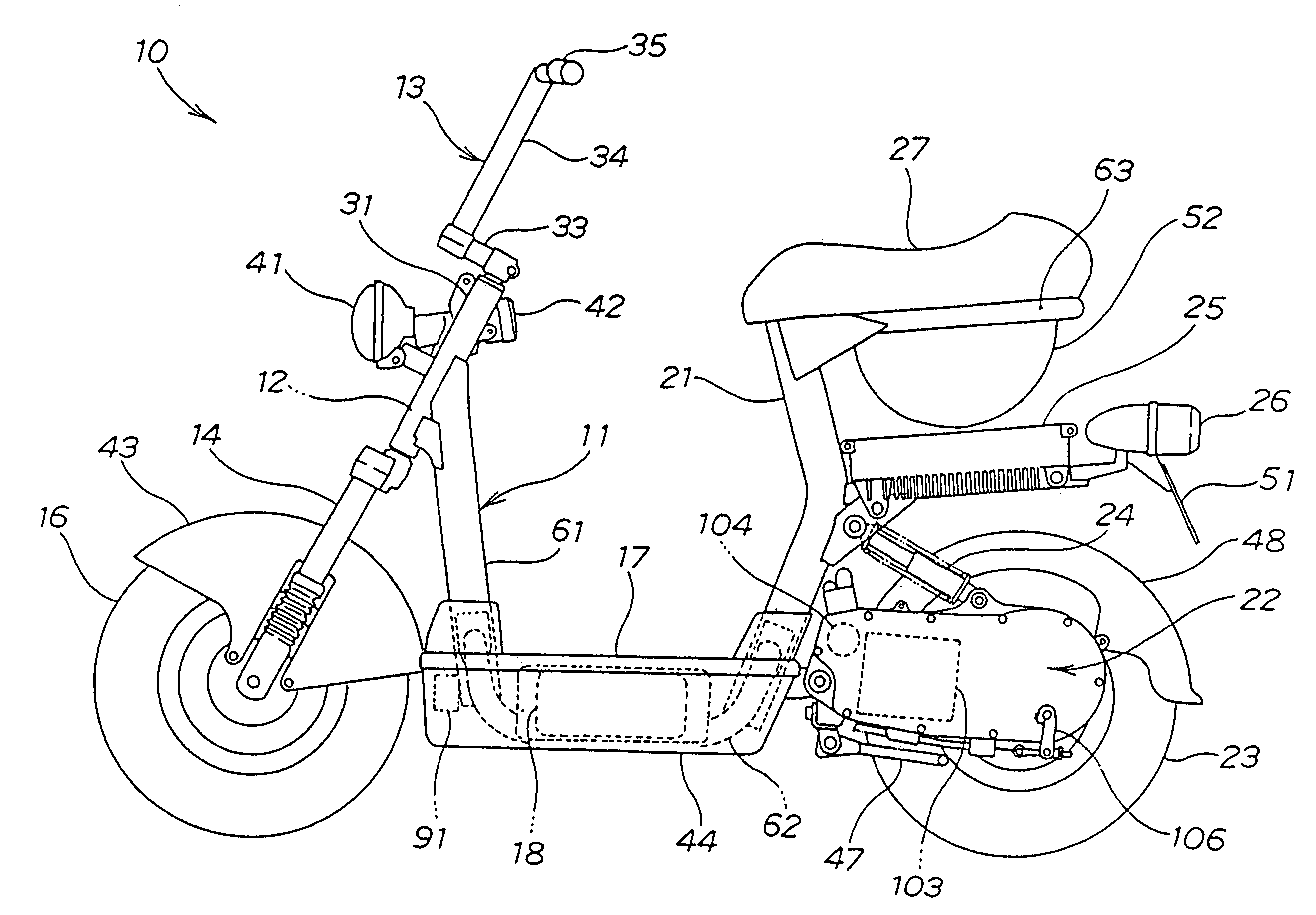
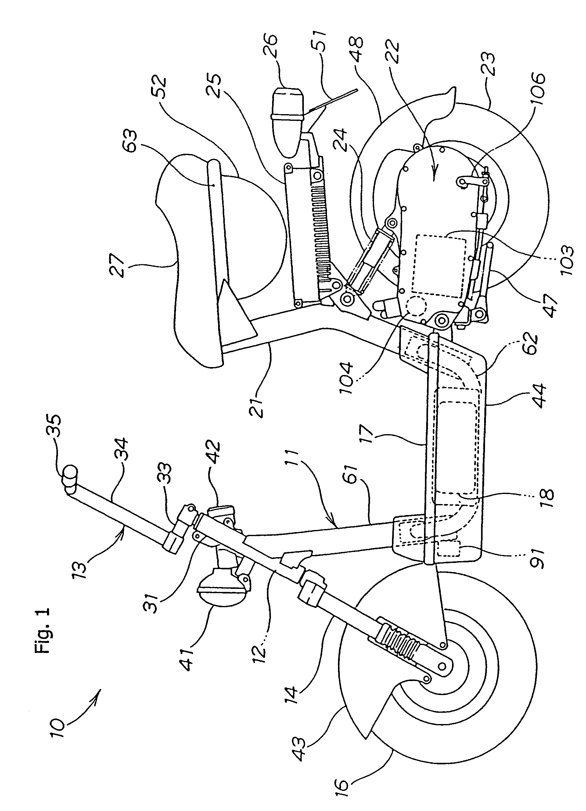
[0092]According to the present invention, a hole section 186 for passing an axle 102 of the rear wheel 23 is provided in the case body 125 where the fins 181 are provided. It is possible to support the axle 102 in the hole section 186 of the case body 125, and it is possible to carry out positioning of the first fins 181 side case body 125 and the rear wheel 21 using the axle 102.

fourth embodiment

[0093]According to the present invention, the cooling apparatus is consists of fins. It is possible to carry natural cooling using traveling air using the fins, and it is possible to reduce weight compared to using forced a cooling apparatus such as a fan.

[0094]FIG. 14 is a cross sectional drawing showing another embodiment of a cooling mechanism for the electronic control module of the present invention. Structural components that are the same as the embodiment shown in FIG. 10 have the same numerals applied and a detailed description is omitted.

[0095]An electronic control module 210 has a heat sink 212 attached to FETs attached inside a case 211, and fourth fins 213 formed on this heat sink 212 is exposed to the outside through the case 211, and is adjacent to the rear wheel, specifically the tire 162.

[0096]In this way, by causing the fourth fins 213 of the heat sink 212 to be exposed to the outside, it is possible to release heat generated by the FETs directly from the fourth fin...


PUM


Abstract

An electric vehicle is provided with a drum brake unit on a rear wheel rotated by drive force of an electric motor. A first set of fins, for cooling the electric motor and the drum brake unit, are provided between the electric motor and the drum brake unit. Specifically, the first set of fins are provided on an inner side surface of a case body. It is possible to cool the electric motor using the first set of fins, and it is also possible to remove heat of the drum brake unit using the first set of fins. The fins act as a heat sink to dissipate heat generated by the drum brake unit, and to resist heat transfer from the drum brake unit to the electric motor, helping to more efficiently cool the electric motor.

Description

CROSS-REFERENCE TO RELATED APPLICATIONS[0001]The present invention claims priority under 35 USC 119 based on Japanese patent applications Nos. 2003-155458, filed May 30, 2003 and 2003-155836, both filed May 30, 2003.[0002]1. Field of the Invention[0003]The present invention relates to an electric vehicle provided with a brake unit on a drive wheel thereof, and to an electronic control module for controlling electrical power supplied to an electric motor. More particularly, the present invention relates to an electric vehicle provided with a brake unit on a drive wheel, wherein cooling is provided for the electric motor and the braking unit, and to an electronic control module for controlling electrical power supplied to an electric motor, where various airflows and components are used to remove heat from the system.[0004]2. Description of the Background Art[0005]As an electric vehicle, it is known to have a controller for carrying out control of an electric motor and electrical equi...

Claims


Application Information

Patent Timeline
IPC IPC(8): B60K1/00H02K11/00B60K1/04B62K11/06B62K11/10B62M7/12
CPCB60K1/00B62K11/06B62K11/10B62M7/12B60L3/0061B60L11/1805B60L11/1877B60K1/04Y02T10/642B60K2001/003B60L2200/12B60Y2200/126B62K2202/00B62K2204/00B60Y2200/12B60L2210/10B60L2210/30B60L2220/44B60L2240/36B60L2240/425B60K2001/006Y02T10/7005Y02T10/705Y02T10/7241Y02T10/7216B60L50/52B60L50/66Y02T10/64Y02T10/70Y02T10/72
Inventor HONDA, SATOSHIKANNO, YOSHIHISA
Owner HONDA MOTOR CO LTD
Why Eureka
Try Eureka