Ink jet break-off length controlled dynamically by individual jet stimulation

a dynamic, ink jet technology, applied in the direction of printing, inking apparatus, other printing apparatus, etc., can solve the problems of not being completely predictable, slightly altering the volume of drops intended for printing or patterning, and far more complex selection of a practical stimulation mechanism for a cij system with many jets

Inactive Publication Date: 2007-07-31
EASTMAN KODAK CO
View PDF28 Cites 20 Cited by
  • Summary
  • Abstract
  • Description
  • Claims
  • Application Information

AI Technical Summary

Problems solved by technology

Such satellites may not be totally predictable or may not always merge with another drop in a predictable fashion, thereby slightly altering the volume of drops intended for printing or patterning.
The several CIJ stimulation approaches disclosed by Sweet '275 may all be practical in the context of a single jet system However, the selection of a practical stimulation mechanism for a CIJ system having many jets is far more complex.
Unfortunately, all of the stimulation methods employing a vibration some component of the printhead structure or a modulation of the common supply pressure result is some amount of non-uniformity of the magnitude of the perturbation applied to each individual jet of a multi-jet CIJ array.
Non-uniform stimulation leads to a variability in the break-off length and timing among the jets of the array.
This variability in break-off characteristics, in turn, leads to an inability to position a common drop charging assembly or to use a data timing scheme that can serve all of the jets of the array.
As the array becomes physically larger, for example long enough to span one dimension of a typical paper size (herein termed a “page wide array”), the problem of non-uniformity of jet stimulation becomes more severe.
Non-uniformity in jet break-off length across a multi-jet array causes unpredictable drop arrival times leading to print quality defects in ink jet printing systems and ragged layer edges or misplaced coating material for other uses of CIJ liquid drop emitters.
However, it appears that the structures that are strong and durable enough to be operated at high ink reservoir pressures contribute confounding acoustic responses that cannot be totally eliminated in the range of frequencies of interest.
While EHD stimulation has been pursued as an alternative to acoustic stimulation, it has not been applied commercially because of the difficulty in fabricating printhead structures having the very close jet-to-electrode spacing and alignment required and, then, operating reliably without electrostatic breakdown occurring.
Also, due to the relatively long range of electric field effects, EHD is not amenable to providing individual stimulation signals to individual jets in an array of closely spaced jets.
However, Eaton does not teach or disclose any multi-jet printhead configurations, nor any practical methods of implementing a thermally-stimulated multi-jet CIJ device, especially one amenable to page wide array construction.
Eaton does not teach or disclose how to configure or operate a thermally-stimulated CIJ printhead that would be needed to print drops an order of magnitude smaller and at substantially higher drop frequencies.

Method used


Image

  • Ink jet break-off length controlled dynamically by individual jet stimulation
  • Ink jet break-off length controlled dynamically by individual jet stimulation
  • Ink jet break-off length controlled dynamically by individual jet stimulation

Examples


Embodiment Construction

[0067]The present description will be directed in particular to elements forming part of, or cooperating more directly with, apparatus in accordance with the present invention. Functional elements and features have been given the same numerical labels in the figures if they are the same element or perform the same function for purposes of understanding the present inventions. It is to be understood that elements not specifically shown or described may take various forms well known to those skilled in the art.

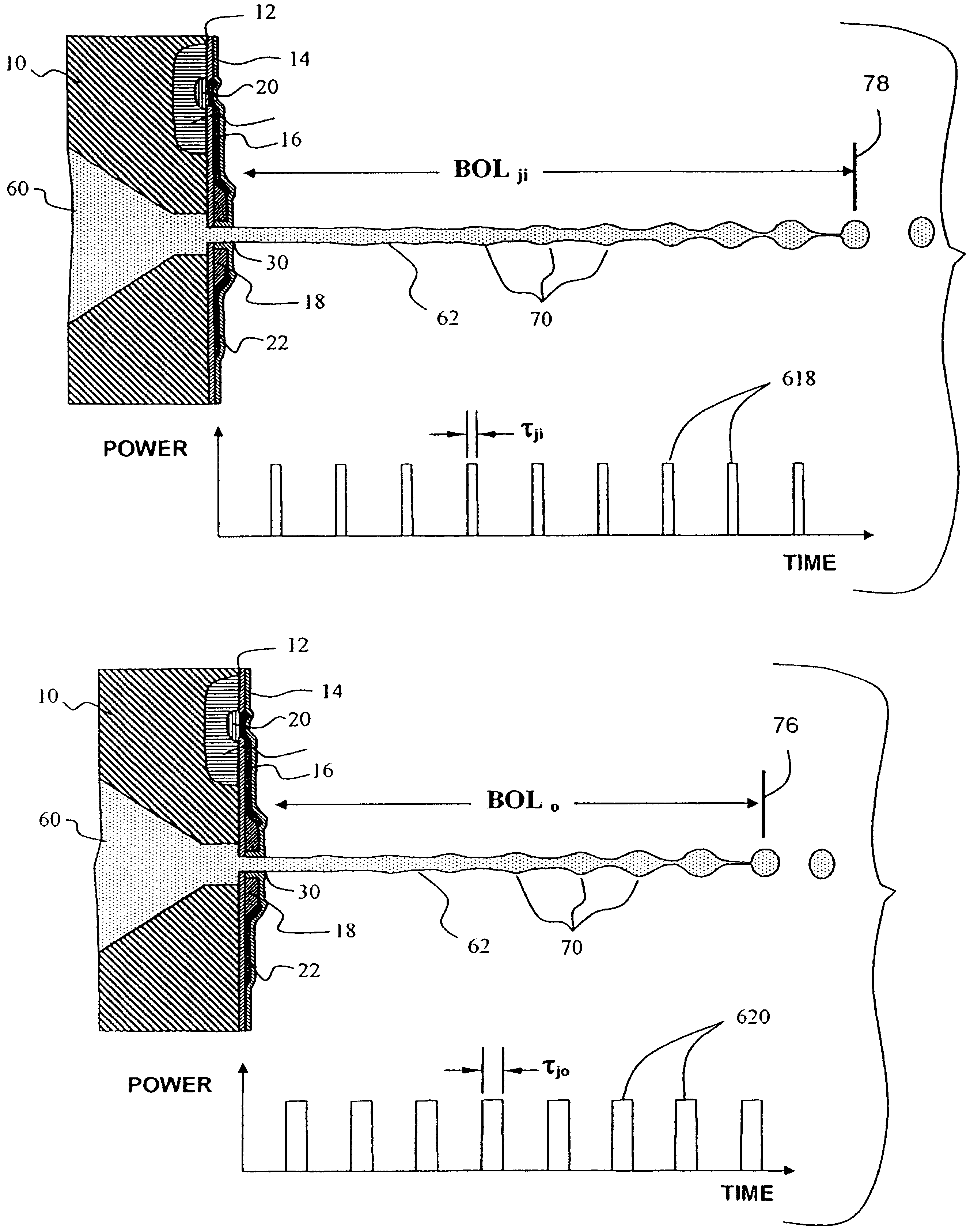
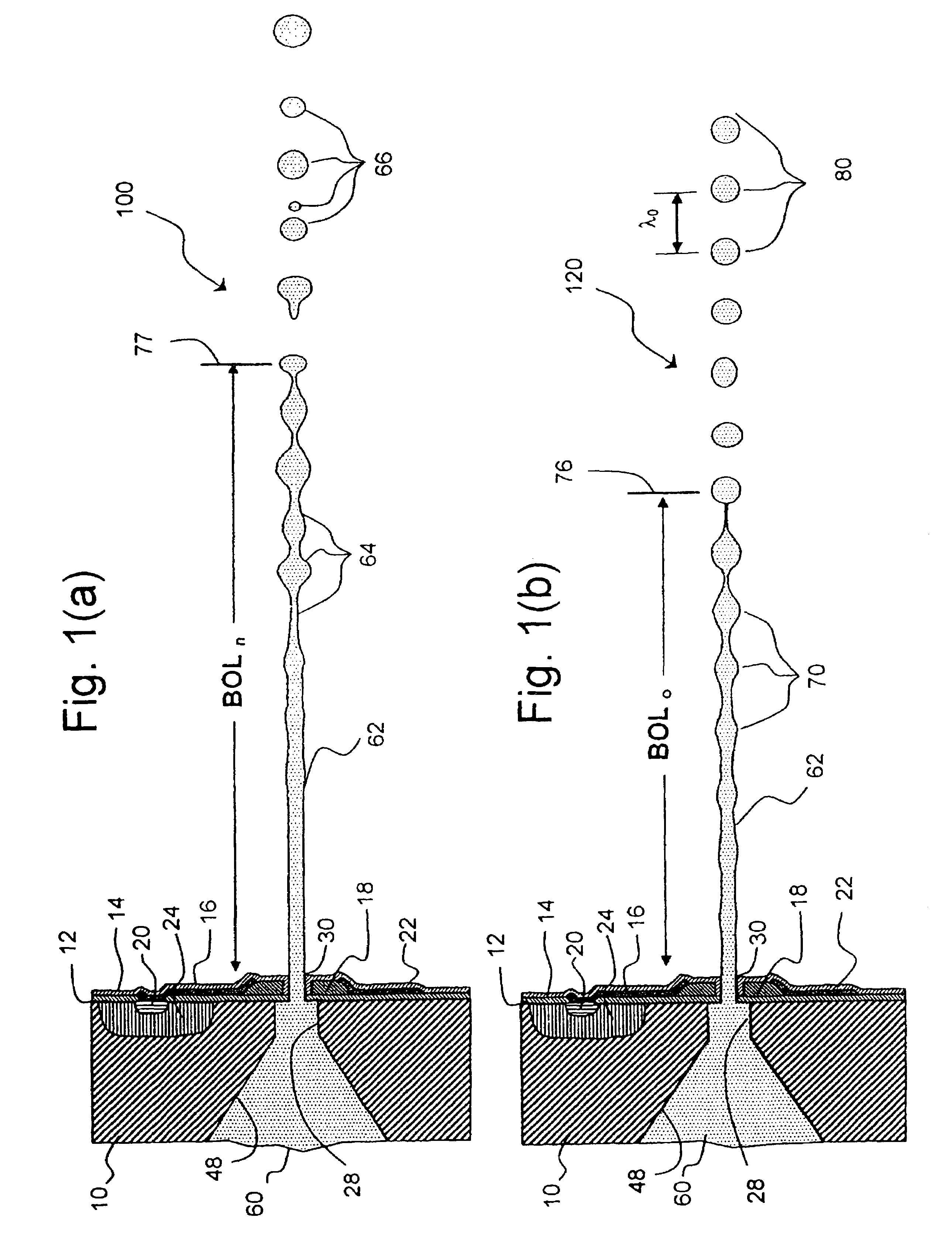
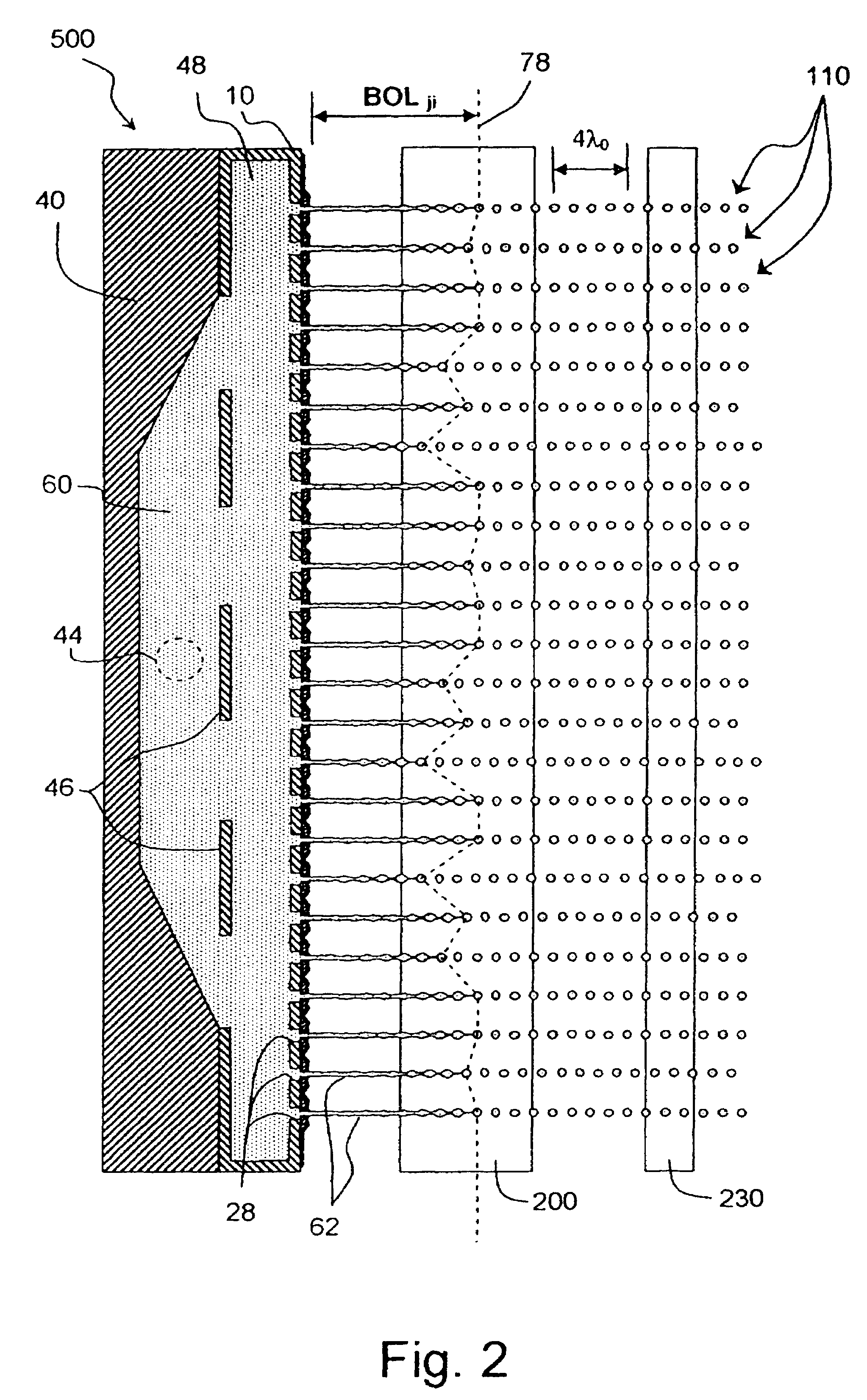
[0068]Referring to FIGS. 1(a) and 1(b), there is shown a portion of a liquid emission apparatus wherein a continuous stream of liquid 62, a liquid jet, is emitted from a nozzle 30 supplied by a liquid 60 held under high pressure in a liquid emitter chamber 48. The liquid stream 62 in FIG. 1(a) is illustrated as breaking up into droplets 66 after some distance 77 of travel from the nozzle 30. The liquid stream illustrated will be termed a natural liquid jet or stream of drops of ...


PUM


Abstract

A jet break-off length control apparatus for a continuous liquid drop emission system is provided. The jet break-off length control apparatus comprises a liquid drop emitter containing a positively pressurized liquid in flow communication with at least one nozzle for emitting a continuous stream of liquid. Resistive heater apparatus is adapted to transfer pulses of thermal energy to the liquid in flow communication with the at least one nozzle sufficient to cause the break-off of the at least one continuous stream of liquid into a stream of drops of predetermined volumes. A sensing apparatus adapted to detect the stream of drops of predetermined volumes is provided. The jet break-off length control apparatus further comprises a control apparatus adapted to calculate a characteristic of the stream of drops of predetermined volumes and adapted to provide a break-off length calibration signal to the resistive heater apparatus wherein the break-off length calibration signal is determined at least by the characteristic of the stream of drops of predetermined volumes. Further apparatus is adapted to inductively charge at least one drop and to cause electric field deflection of charged drops. The present inventions are additionally configured to control break-off lengths for a plurality of streams of drops of predetermined volumes by determining a break-off length calibration signal that contains information specific to the plurality of streams of drops of predetermined volumes. Jet stimulation apparatus comprised of a plurality of thermomechanical or electromechanical transducer devices that transfer mechanical energy to the fluid are claimed. Methods of controlling the jet break-off length are also disclosed.

Description

CROSS REFERENCE TO RELATED APPLICATIONS[0001]Reference is made to commonly assigned, U.S. patent application Ser. No. 11 / 229,454 filed concurrently herewith, entitled “INK JET BREAK-OFF LENGTH MEASUREMENT APPARATUS AND METHOD,” in the name of Gilbert A. Hawkins, et al.; U.S. patent application Ser. No. 11 / 229,261 filed concurrently herewith, entitled “CONTINUOUS INK JET APPARATUS AND METHOD USING A PLURALITY OF BREAK-OFF TIMES,” in the name of Michael J. Piatt, et al.; U.S. patent application Ser. No. 11 / 229,263 filed concurrently herewith, entitled “CONTINUOUS INK JET APPARATUS WITH INTEGRATED DROP ACTION DEVICES AND CONTROL CIRCUITRY,” in the name of Michael J. Piatt, et al.; U.S. patent application Ser. No. 11 / 229,459 filed concurrently herewith, entitled “METHOD FOR DROP BREAKOFF LENGTH CONTROL IN A HIGH RESOLUTION,” in the name of Michael J. Piatt et al.; and U.S. patent application Ser. No. 11 / 229,456 filed concurrently herewith, entitled “IMPROVED INK JET PRINTING DEVICE WITH...

Claims


Application Information

Patent Timeline
Patent Type & Authority Patents(United States)
IPC IPC(8): B41J29/393
CPCB41J2/03B41J2002/022B41J2002/033B41J2202/13B41J2202/16
Inventor HAWKINS, GILBERT A.POND, STEPHEN F.PIATT, MICHAEL J.
Owner EASTMAN KODAK CO
Why Eureka
Try Eureka