Internal connection dental implant

a technology of dental implants and internal connections, applied in dental implants, dental surgery, medical science, etc., can solve problems such as implant connection failures that continue to exist, and achieve the effects of reducing implant connection failures, and increasing torque carrying capacity

Active Publication Date: 2007-07-31
KEYSTONE DENTAL INC
View PDF37 Cites 87 Cited by
  • Summary
  • Abstract
  • Description
  • Claims
  • Application Information

AI Technical Summary

Benefits of technology

[0007]In general, the dental implant of the present invention includes a drive or indexing region which equalizes the stress distribution and provides for increased torque carrying capacity across the entire implant connection, thereby providing a drive means which minimizes implant connection failures and which is usable for all sizes of implants. The implant in accordance with the present invention also includes a stabilizing region which provides the implant and abutment with a highly stable connection.
[0008]In the preferred embodiment, the drive and indexing region includes a plurality of equally dimensioned and equally configured concave and convex lobes which are positioned between a minor diameter and a major diameter. This lobed configuration provides increased surface area for contact with a wrench or other drive means during installation, as well as providing an outer implant wall of sufficient thickness to improve resistance to implant connection failures, particularly when accommodating off-axis loading.
[0009]In the preferred embodiment, the stabilizing region for minimizing relative movement, so called micromotion, between the implant and a corresponding abutment, and thus improving stability between the implant and such abutment, includes a beveled surface positioned between the drive and indexing section and the proximal end of the implant. This beveled surface mates with a corresponding beveled surface of the abutment. The angle of this beveled surface is sufficient to form a friction fit so as to stabilize the interface between the implant and the abutment.
[0010]Accordingly, it is an object of the present invention to provide an internal connection dental implant and assembly facilitating improved rotational or drive torque, while at the same time minimizing failures of the implant connection during installation and use.
[0011]Another object of the present invention is to provide an internal connection dental implant and assembly which provides stability between the implant and the corresponding abutment.

Problems solved by technology

While many internally driven dental implants provide satisfactory torque transfer and stability between implant and abutment, implant connection failures continue to exist.

Method used


Image

  • Internal connection dental implant
  • Internal connection dental implant
  • Internal connection dental implant

Examples


Embodiment Construction

[0029]The present invention is directed to a dental implant and a dental implant assembly and more specifically to an internal drive or internal connection implant and a corresponding dental implant assembly.

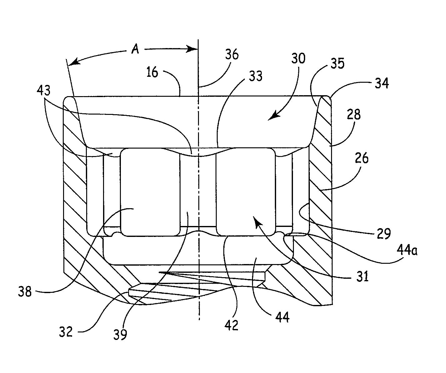
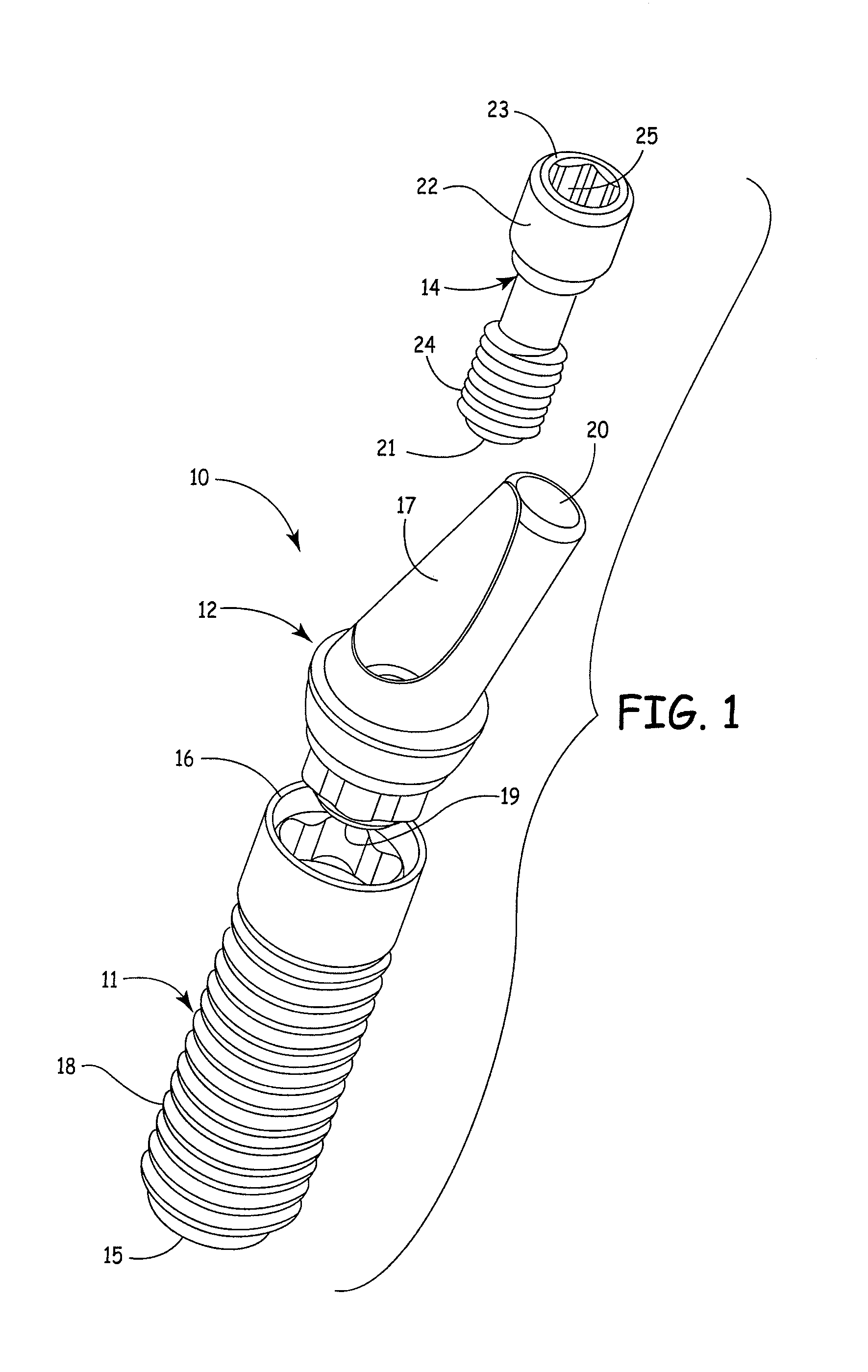
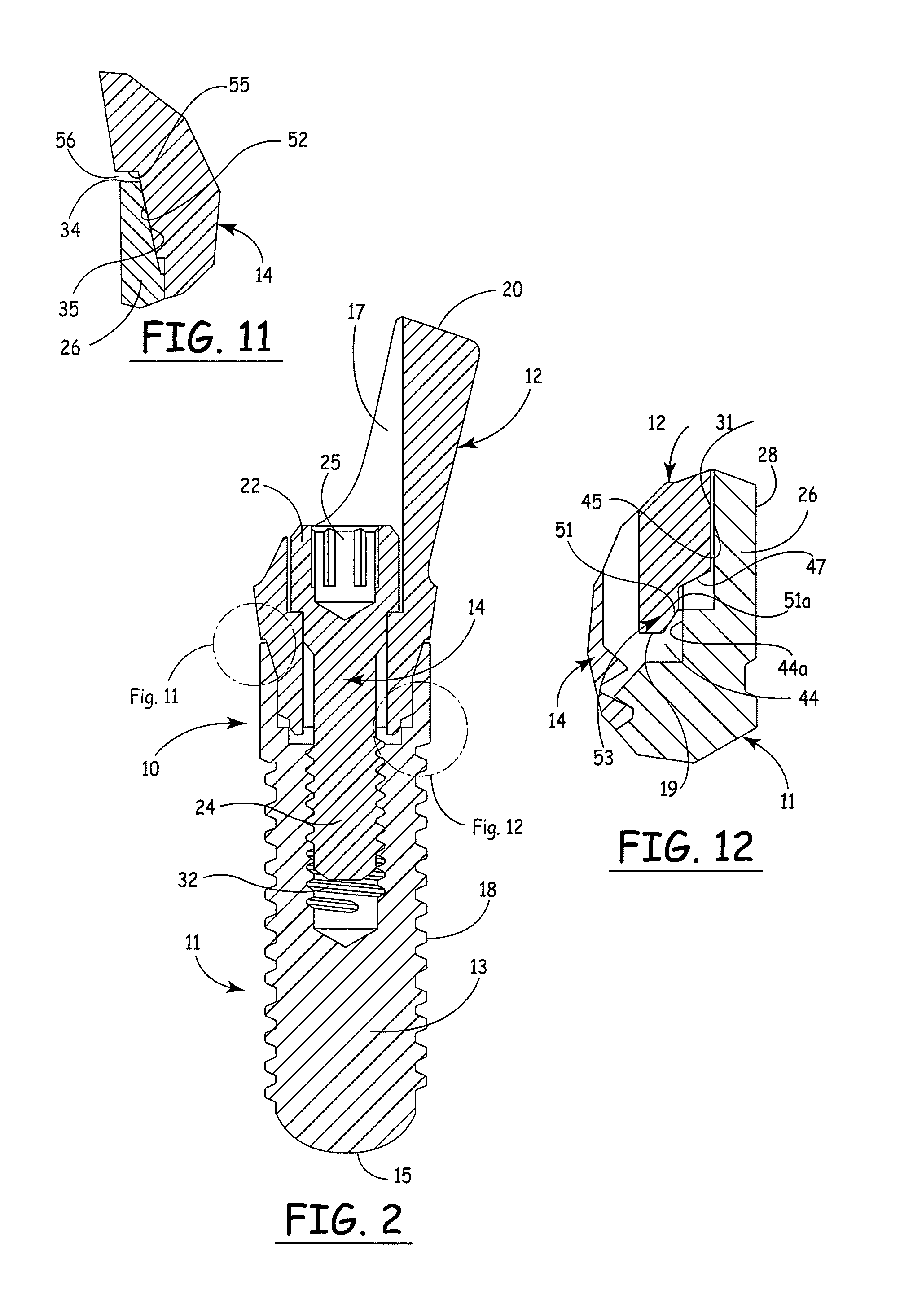
[0030]Reference is first made to FIGS. 1 and 2 showing the dental implant assembly 10 in broken apart form (FIG. 1) and in assembled or connected form (FIG. 2). The dental assembly 10 includes a dental implant 11, an abutment 12 and an abutment or connection screw 14. The dental implant 11 includes a distal end 15, a proximal end 16, a body portion 13 and a plurality of external threads 18 on the body. The abutment includes a distal end 19, a proximal end 20 and an internal connection bore or opening 17. The connection screw 14 includes a distal end 21 and a proximal end 23. The screw 14 is provided with a plurality of external threads 24 near its distal end 21 and a head 22 near its proximal end 23. The head 22 is provided with wrench engaging means 25 such as an internal hex, ...


PUM


Abstract

An internal connection dental implant and implant assembly in which the implant includes a lobed configuration for installing the implant and a beveled surface positioned on the proximal side of the lobed configuration for providing stability between the implant and a corresponding abutment.

Description

BACKGROUND OF THE INVENTION[0001]1. Field of the Invention[0002]The present invention relates generally to the field of dental implants and more specifically to an internal connection implant. The invention also relates to the combination of an internal connection implant and a complementary abutment.[0003]2. Description of the Prior Art[0004]A wide variety of dental implants currently exists in the art. Such dental implants commonly include a body with external threads for mounting and retaining the implant within the patient's mouth. Installation of the implant involves rotation of the implant into a predrilled or tapped site using a drive member such as a ratchet or other rotation means. The implant also includes a drive region which may be located externally or internally. Various structures for both externally and internally driving the implant currently exist.[0005]While many internally driven dental implants provide satisfactory torque transfer and stability between implant a...

Claims


Application Information

Patent Timeline
Patent Type & Authority Patents(United States)
IPC IPC(8): A61C8/00
CPCA61C8/005A61C8/0066A61C8/0069A61C8/0054A61C8/0068A61C8/0071A61C8/00
Inventor CARTER, ROBERT D.
Owner KEYSTONE DENTAL INC
Why Eureka
Try Eureka