
Encapsulated fastener and method and tooling for manufacturing same

a technology of encapsulated fasteners and tools, applied in the field of fasteners, can solve the problems of ineffective solutions in highly corrosive liquid environments, high cost of materials, and high risk of corrosion, and achieve the effects of reducing the risk of corrosion, and reducing the cost of materials

Active Publication Date: 2007-07-31
THOMPSON STEVEN L
View PDF9 Cites 15 Cited by
  • Summary
  • Abstract
  • Description
  • Claims
  • Application Information

AI Technical Summary

Benefits of technology

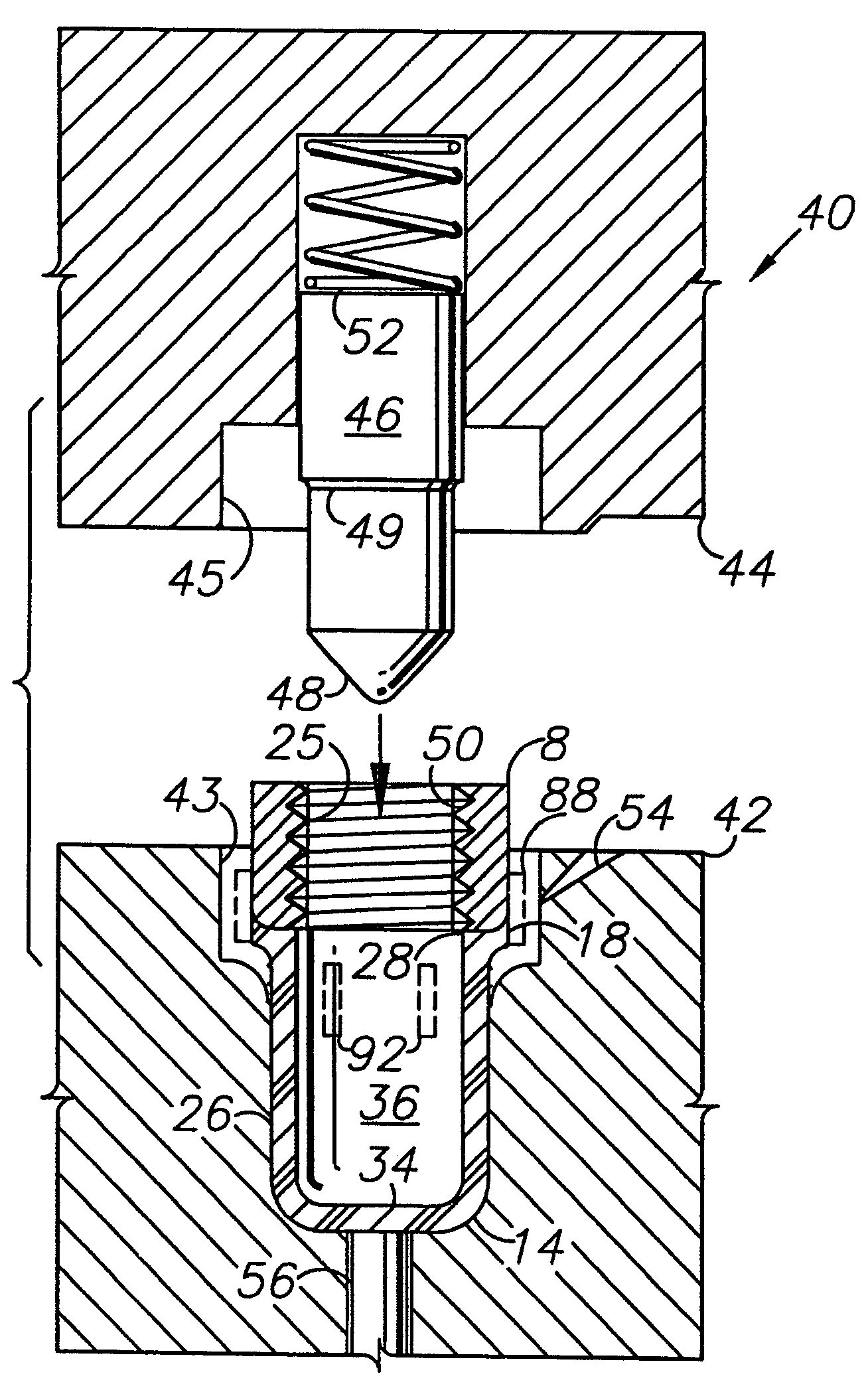
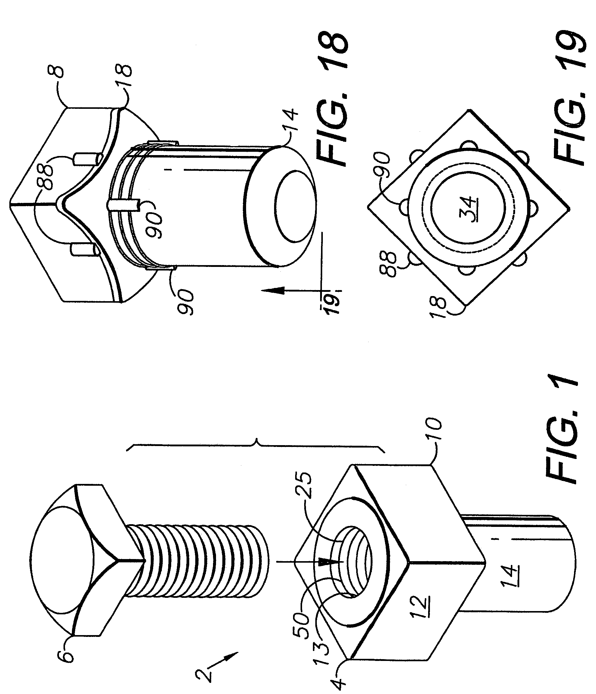
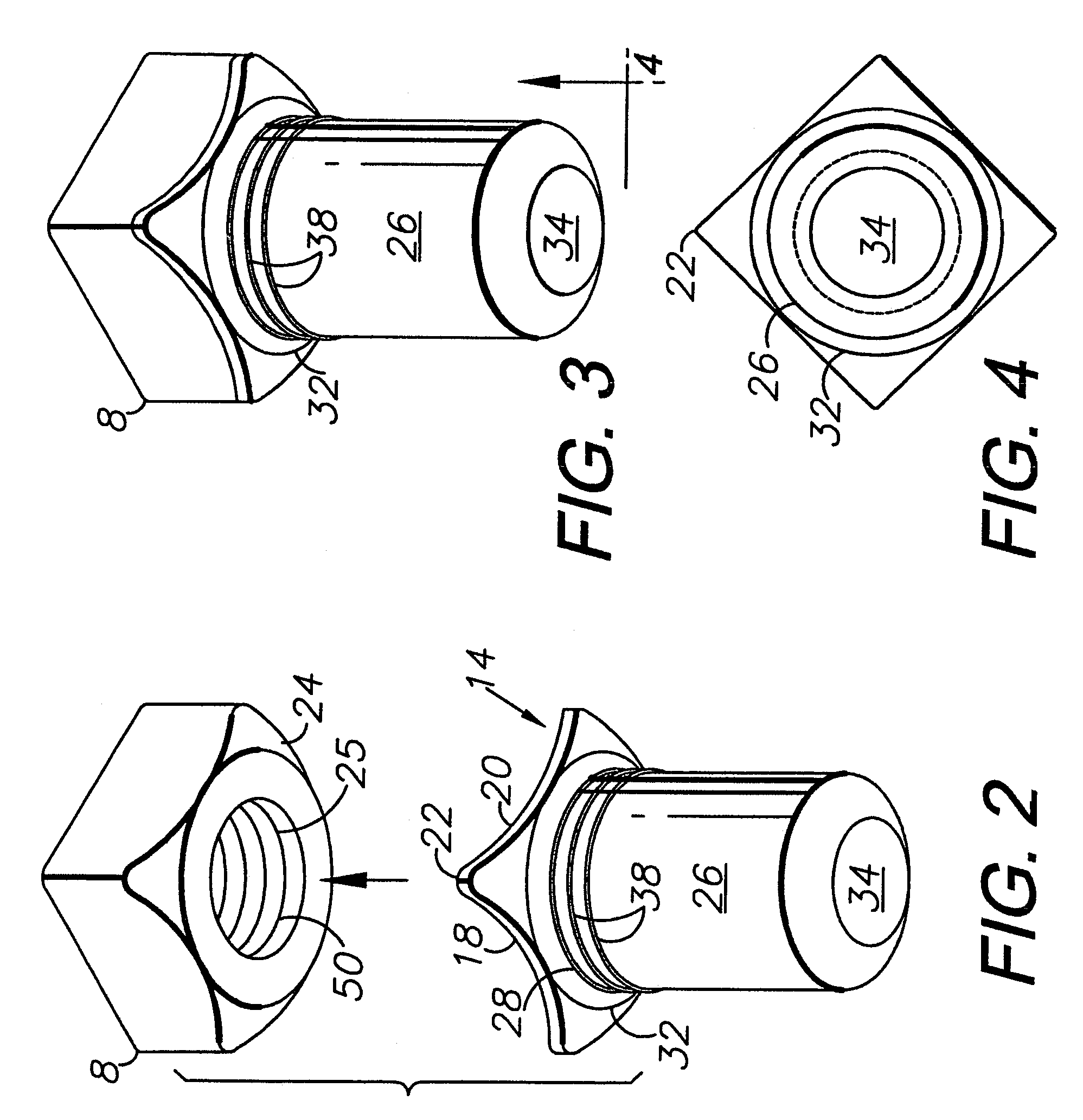
"The present invention provides an encapsulated fastener that includes a two-part encapsulation comprising a base and an extension. The manufacturing method involves injection molding the encapsulation extension and placing it on a nut, followed by overmolding the base over the nut and a portion of the extension with tooling embodying another aspect of the invention. The technical effect of this invention is to provide a fastener that is secure and durable, with improved resistance to corrosion and damage."

Problems solved by technology

Although steel is a logical material choice for many fasteners based on high strength and low cost, many steel alloys are susceptible to rust, corrosion and galvanic action.
However, such materials tend to be relatively expensive or ineffective in applications requiring the cost-effectiveness and material strength of steel.
However, such solutions can be ineffective in highly corrosive liquid environments, such as salt water, wastewater, process chemicals, acid compounds and base compounds.
However, such specialized fasteners tend to be more expensive than standard-size nuts.
Problems with such encapsulation configurations include misalignment between bolt and extension internal threads and unsupported extensions when the extension bores are oversized to avoid contact with the bolt shafts received therein.

Method used


Image

  • Encapsulated fastener and method and tooling for manufacturing same
  • Encapsulated fastener and method and tooling for manufacturing same
  • Encapsulated fastener and method and tooling for manufacturing same

Examples


Embodiment Construction

I. Introduction and Environment

[0032]As required, detailed embodiments of the present invention are disclosed herein; however, it is to be understood that the disclosed embodiments are merely exemplary of the invention, which may be embodied in various forms. Therefore, specific structural and functional details disclosed herein are not to be interpreted as limiting, but merely as a basis for the claims and as a representative basis for teaching one skilled in the art to variously employ the present invention in virtually any appropriately detailed structure.

[0033]Certain terminology will be used in the following description for convenience in reference only and will not be limiting. For example, up, down, front, back, right and left refer to the invention as oriented in the view being referred to. The words “inwardly” and “outwardly” refer to directions toward and away from, respectively, the geometric center of the embodiment being described and designated parts thereof. Said term...


PUM

PropertyMeasurementUnit
sizeaaaaaaaaaa
areaaaaaaaaaaa
strengthaaaaaaaaaa

Abstract

An encapsulated fastener includes a nut adapted to receive a bolt. The nut is encapsulated by an encapsulation including an extension, which includes a tube adapted for receiving a portion of the bolt and a flange adapted for engaging a face of the nut. The encapsulation extension is placed on the nut in an overmolding tool, wherein an encapsulation base is injection molded over a portion of the encapsulation extension. The encapsulation base encapsulates the nut, except for its bore, which is sealed off during the overmolding process by a spring-mounted mandrel. Alternative embodiments of the invention include tubes with different configurations for contacting the bolt whereby the tube or cylinder is reinforced. A method and tooling for manufacturing the encapsulated fastener are also provided.

Description

BACKGROUND OF THE INVENTION[0001]1. Field of the Invention[0002]The present invention relates generally to fasteners, and in particular to an encapsulated fastener and a method and tooling for manufacturing same.[0003]2. Description of the Related Art[0004]Mechanical fasteners are available in a wide variety of designs, which accommodate various objects being joined. The specific fastener design features are generally determined by such criteria as the functional requirements of the applications, the static and dynamic loads imposed thereon, the materials being fastened and the operating environment.[0005]Threaded fasteners include bolts, nuts, screws, threaded rods and the like. An advantage of such fasteners is that they can be tightened and loosened with readily available hand and power tools. Consequently, threaded fasteners are used extensively in construction, manufacturing and other industries.[0006]Although steel is a logical material choice for many fasteners based on high ...

Claims


Application Information

Patent Timeline
Patent Type & Authority Patents(United States)
IPC IPC(8): B21D53/24
CPCF16B37/14
Inventor THOMPSON, STEVEN L.
Owner THOMPSON STEVEN L
Learn More