Encoder output signal correction apparatus and method

a signal correction and encoder technology, applied in the direction of instruments, code conversion, transmission systems, etc., can solve the problems of large measurement errors, insufficient accuracy, and ill effect of deviation from ideal sinusoidal waves on interpolation accuracy, so as to improve the robustness against higher harmonic component errors and improve the interpolation accuracy in the interpolator

Active Publication Date: 2007-07-31
MITUTOYO CORP
View PDF14 Cites 22 Cited by
  • Summary
  • Abstract
  • Description
  • Claims
  • Application Information

AI Technical Summary

Benefits of technology

[0016]In the present invention, an error from the ideal Lissajous waveform contained in the two-phase sinusoidal signals corrected at the corrector means is detected, and the detected error is added to an accumulatively added last value to yield a new correction coefficient, thereby dynamically updating the correction coefficient. Accordingly, the computation of error parameters of the Lissajous waveform requires no complicated process and leads to possible fast convergence. Therefore, it is possible to improve the interpolation accuracy in an interpolator. It is also possible to improve robustness against higher harmonic component errors due to non-uniformity of scales and non-uniformity of alignments in an encoder.

Problems solved by technology

Accordingly, a deviation from an ideal sinusoidal wave exerts an ill effect on the interpolation accuracy.
When the two-phase sinusoidal signals with such the fluctuating distortion factor is employed in measurements, a large measurement error arises.
The technology of JP-A 3-48122 reduces the waveform distortion to some extent though the accuracy is not sufficient for application to position measurements in precise machining or the like.
The system of JP Patent No. 2695623 requires precise creation of a duty factor between light and dark portions while the precise creation is difficult in a fine scale.

Method used


Image

  • Encoder output signal correction apparatus and method
  • Encoder output signal correction apparatus and method
  • Encoder output signal correction apparatus and method

Examples


Embodiment Construction

[0029]Embodiments of the present invention will now be described in detail with reference to the drawings.

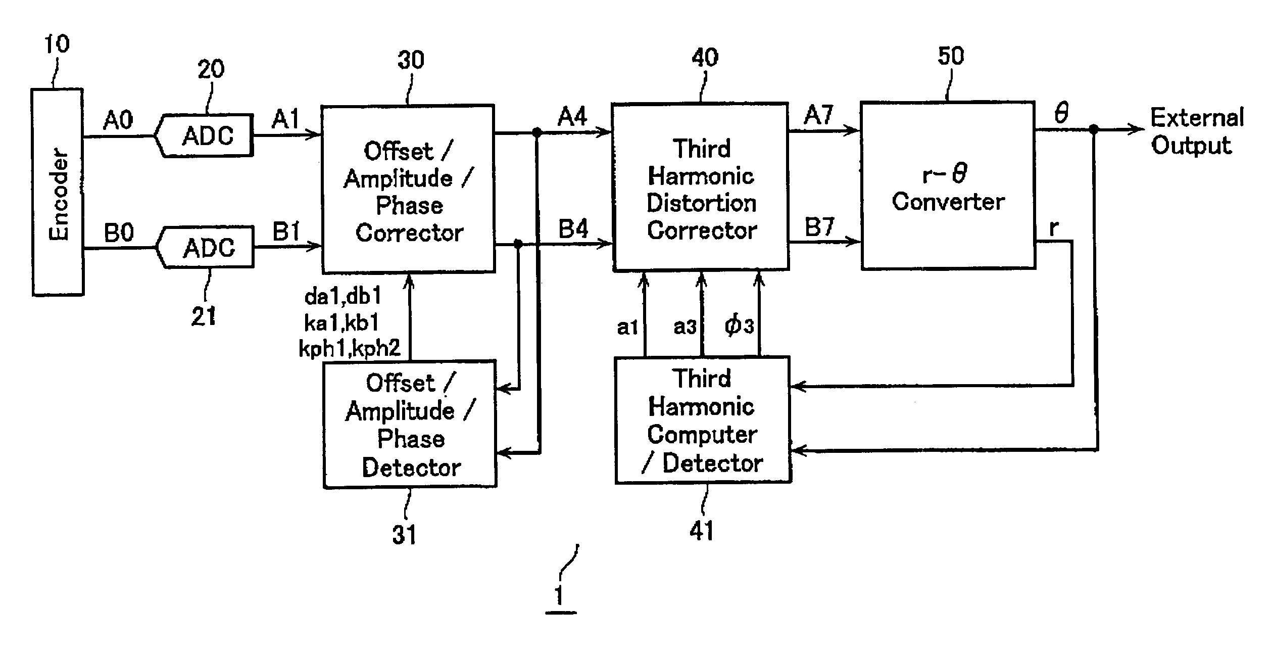
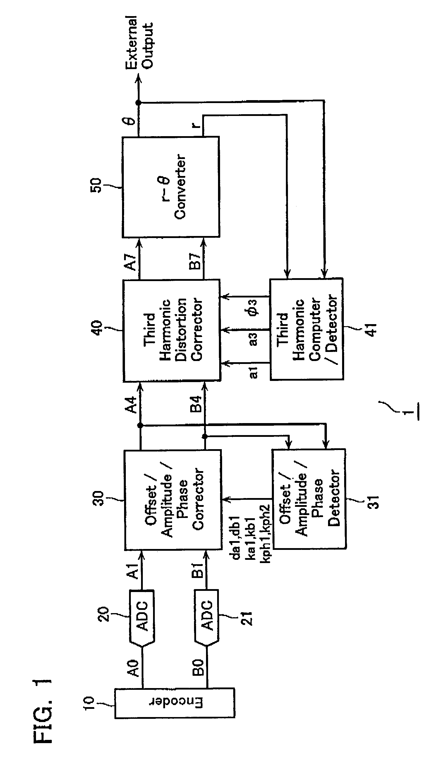
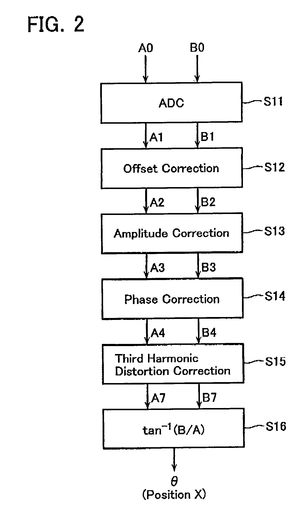
[0030]FIG. 1 is a block diagram showing a basic configuration of an encoder output signal correction device 1 according to an embodiment of the present invention. The encoder output signal correction device 1 comprises A / D converters 20, 21, an offset / amplitude / phase corrector 30, an offset / amplitude / phase detector 31, a third harmonic distortion corrector 40, a third harmonic computer / detector 41, and an r-θ converter 50, This device is operative to correct output signals A0, B0 from the encoder 10 to remove a third harmonic distortion therefrom.

[0031]The encoder 10 may be of the photoelectric type or the magnetic type, for example, without distinction of detection principle. The A-, and B-phase sinusoidal signals A0, B0 output from the encoder 10 may usually contain an amplitude error, a phase error, an offset and a third harmonic distortion.

[0032]The signals A0, B0 are sample...


PUM


Abstract

An offset error, an amplitude error, a phase error and a third harmonic component contained in two-phase sinusoidal signals are removed using relatively simple digital computations. An offset error contained in two-phase sinusoidal signals with a phase difference output from an encoder is detected and corrected. Then, an amplitude error contained in the offset-corrected two-phase sinusoidal signals is detected and corrected. Subsequently, a phase error contained in the amplitude-corrected two-phase sinusoidal signals is detected and corrected. Further, a third harmonic distortion contained in the phase-corrected two-phase sinusoidal signals is detected and corrected. Each correction step includes detecting an error from an ideal Lissajous waveform contained in the corrected two-phase sinusoidal signals, and adding the detected error to an accumulatively added last value to yield a new correction coefficient, thereby dynamically updating the correction coefficient.

Description

CROSS-REFERENCE TO RELATED APPLICATION[0001]This application is based on and claims the benefit of priority from prior Japanese Patent Application No. 2004-299001, filed on Oct. 13, 2004, the entire contents of which are incorporated herein by reference.BACKGROUND OF THE INVENTION[0002]1. Field of the Invention[0003]The present invention relates to an encoder output signal correction apparatus and method for correcting two-phase sinusoidal signals output from an encoder that detects positions, angles, velocities, angular velocities and so forth.[0004]2. Description of the Related Art[0005]An interval between gratings formed on a scale in an encoder is limited to process. In order to measure a finer interval than that between the scale gratings, the spatial period of a phase variation in a sinusoidal signal output from the encoder should be divided much finer and interpolated. A variety of interpolators have been employed in the art. For example, a digitized interpolator comprises an...

Claims


Application Information

Patent Timeline
Patent Type & Authority Patents(United States)
IPC IPC(8): H03M1/48
CPCG01D5/24452G01D5/24495G01D5/2449G01D5/2448G01D18/001
Inventor KIRIYAMA, TETSUROKOISO, RYUICHIYOSHINAKA, TOSHIROU
Owner MITUTOYO CORP
Why Eureka
Try Eureka