
Image formation apparatus having a body to be charged with specified properties and including the use of a protective material

a technology of image formation apparatus and body, which is applied in the direction of electrographic process apparatus, corona discharge, instruments, etc., can solve the problems of deterioration of photoconductor surface in the charging process, inability to prevent chemical deterioration of photoconductor surface, and inability to achieve high-quality image output stably over a long period of time, and achieve excellent abrasive resistance and image quality stability. , the effect of suppressing chemical deteriora

Active Publication Date: 2007-07-31
RICOH KK
View PDF33 Cites 44 Cited by
  • Summary
  • Abstract
  • Description
  • Claims
  • Application Information

AI Technical Summary

Benefits of technology

The present invention provides an image formation apparatus that uses a charging process of proximity discharge to suppress chemical deterioration of the surface of a body to be charged, and to prevent image quality degradation in repeated use of the photoconductor. The apparatus has excellent abrasive resistance and stability of image quality, and can output a high quality image stably over a long period of time. The apparatus includes a moving body to be charged, a charging device for charging the body to be charged, a latent image formation device for forming a latent image on the surface of the body to be charged, and a development device for depositing toner on the image portion of the latent image formed by the latent image formation device. The apparatus also includes a protective material feeding device for depositing a protective material on at least a discharge area of the surface of the body to be charged. The process cartridge for the image formation apparatus integrates the body to be charged and at least one device selected from the group consisting of the charging device, the latent image formation device, the development device, the toner elimination device, and the protective material feeding device.

Problems solved by technology

Recently, the attainment of high quality image and miniaturization of the apparatus has been increasingly desired and the attainment of high quality image and miniaturization of the charging device has been problematic.
However, it is found that the photoconductor surface is deteriorated in the charging process due to the proximity discharge, since the discharge concentrates in proximity to the photoconductor surface.
However, such a structure can improve the resistance to a mechanical abrasion but cannot prevent the chemical deterioration of the photoconductor surface caused by the proximity discharge.
In this case, since the photoconductor surface becomes difficult to be refaced by improving the mechanical abrasive resistance, a matter of the photoconductor surface, which is deteriorated by the proximity discharge, becomes easy to remain and it causes the generation of an image deletion or each kind of an image defect.
Recently, proximity discharge prevails in a charging device used in an image formation apparatus and the influence of chemical deterioration caused by the proximity discharge cannot be avoided.
Therefore, the aforementioned method for improving the mechanical abrasive resistance of a photoconductor causes the elimination of a deteriorated matter on a photoconductor surface to be difficult and accelerates the generation of an image defect, and, in fact, the attainment of long life of the photoconductor has not been achieved yet.
Furthermore, it is found that taking only the improvement of the mechanical abrasive resistance of the photoconductor reduces the resistance of a cleaning blade and inadequate cleaning or the generation of filming tends to be induced.

Method used


Image

  • Image formation apparatus having a body to be charged with specified properties and including the use of a protective material
  • Image formation apparatus having a body to be charged with specified properties and including the use of a protective material
  • Image formation apparatus having a body to be charged with specified properties and including the use of a protective material

Examples


specific embodiment 1

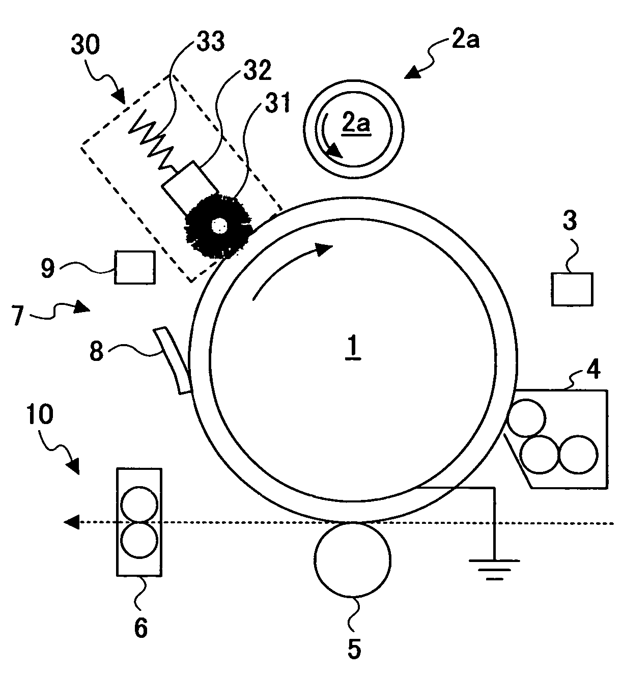
[0057]A specific embodiment 1 of an image formation apparatus to which the present invention is applied is described below. However, this is one example of the present invention and the present invention is not limited to this embodiment. FIG. 5 illustrates one example of an image formation apparatus having a structure common to each example described below. The image formation apparatus has a photoconductor 1 as an image supporter that is made of an organic photoconductor. The photoconductor 1 is characterized by, at least, having an elastic displacement ratio τe equal to or greater than 40%.

[0058](Overall Structure)

[0059]In FIG. 5, the photoconductor 1 is rotationally driven using a driving device not shown in the figure and the surface of it is charged to a predetermined polarity by a charging roller 2a of a charging device 2 that uses a proximity charging process. The charged surface of the photoconductor 1 is exposed to light by using a latent image formation device 3 and a lat...


PUM


Abstract

An image formation apparatus including at least a moving body to be charged, a charging device for charging the body to be charged using discharge caused by applying a voltage to a charging member provided in contact with or proximity to the body to be charged, a latent image formation device for forming a latent image on a surface of the body to be charged which is charged by the charging device, and a development device for depositing toner on an image portion of the latent image formed by the latent image formation device, wherein an elastic displacement ratio τe for the surface of the body to be charged is equal to or greater than 40% which is defined by the following formula,elastic displacement ratio τe (%)=[(maximum displacement)-(plastic displacement)] / (maximum displacement)×100,and the image formation apparatus further includes a protective material feeding device for depositing a protective material on at least a discharge area of the surface of the body to be charged.

Description

BACKGROUND OF THE INVENTION[0001]1. Field of the Invention[0002]The present invention relates to an image formation apparatus using an electrophotographic process and a process cartridge for an image formation apparatus.[0003]2. Description of the Related Art[0004]Conventionally, an image formation apparatus using an electrophotographic process has a charging device for charging the surface of a photoconductor as a body to be charged. One type of charging process used in the charging device is a charging process based on proximity discharge. In this process, the photoconductor surface is charged due to the proximity discharge by contacting a charging member with the photoconductor surface or arranging a charging member close to the photoconductor surface without contact.[0005]Recently, the attainment of high quality image and miniaturization of the apparatus has been increasingly desired and the attainment of high quality image and miniaturization of the charging device has been pro...

Claims


Application Information

Patent Timeline
Patent Type & Authority Patents(United States)
IPC IPC(8): G03G15/00G03G15/02G03G15/18G03G21/00G03G5/07G03G21/18
CPCG03G5/0546G03G5/0614G03G5/0679G03G5/14734G03G5/14791G03G15/751G03G21/0058
Inventor TAMOTO, NOZOMUSUZUKI, TETSUROSUZUKI, YASUOTOKUMASU, TAKAHIKOWATANABE, KAZUHIKONAKAI, HIROSHIOHSHIMA, KOHICHITSUKUDE, NOBORUMATSUURA, NEKKA
Owner RICOH KK
Learn More