
Flexible scanning and sensing platform

Active Publication Date: 2007-07-31
SYST TO ASIC
View PDF9 Cites 6 Cited by
  • Summary
  • Abstract
  • Description
  • Claims
  • Application Information

AI Technical Summary

Benefits of technology

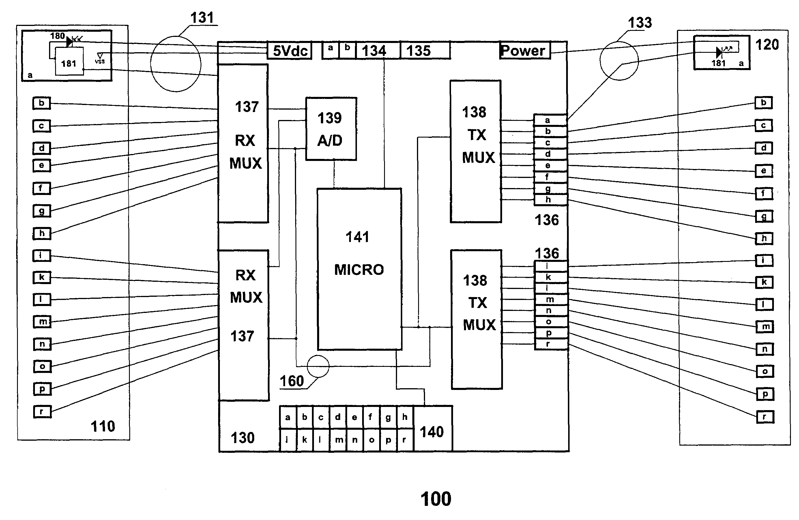
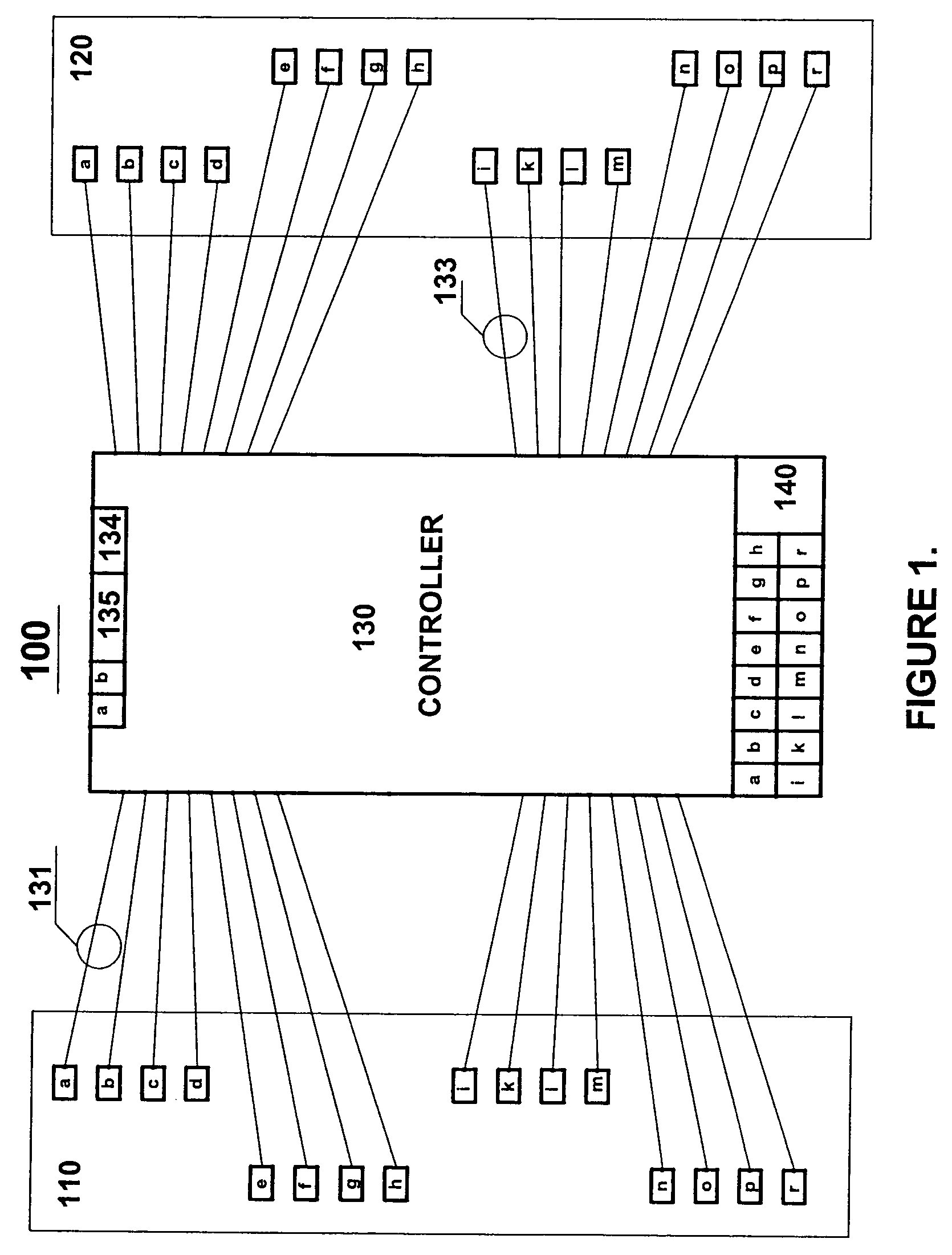
[0008]The disclosed embodiments of the present invention overcome many of the foregoing problems by providing a low cost Flexible Scanner and Sensor (FLEXI) architecture as will be described hereinafter. In accordance with one embodiment of the present invention, a flexible scanning and sensing platform is provided that includes a controller and a plurality of remote sensor units, each containing sensor elements, connected to the controller by means of cable, such as a twisted pair. The remote units can be operated in opposed or proximity mode, in either synchronous or asynchronous manner, and can be adapted to perform any type of sensing including photoelectric, inductive, capacitive, magnetic, IR, ultrasound, RF, temperature, pressure, PIR, etc. The remote units can be positioned to achieve custom detection profiles and resolutions that are optimized for a given application. Furthermore, custom profiles and resolutions can be achieved by alteration of scanning sequences used by the controller. Control of scan frequencies allows remote units in one area of the detection profile to operate at a different effective response time than remote units in other areas of the detection profile, thus providing for a degree of control required by multi-mode sensor and scanner applications. These and other advantages allow FLEXI to provide cost effective, enhanced performance solutions to the areas of industrial sensing and scanning that have not been achieved by present art sensors and scanners.

Problems solved by technology

One of the limitations of present scanner architectures is that the distance between the transducer elements within each bar is fixed, and consequently so is the dimension of the detection profile.
Furthermore, the user is not able to customize beam location and is therefor unable to achieve a desired mix of resolutions and detection profiles.
These restrictions dramatically increase cost and drastically reduce overall penetration of the scanner technology into industrial sensing applications.
The complexity and cost, as well as multiple potential failure points of such an installation, limits the use of such present scanners to areas where no alternatives are practical.
Mechanical installation requirements of present scanners, which tend to be large and bulky, are incompatible with relatively small areas allocated to sensing equipment and therefor further limit penetration of the scanners into applications traditionally dominated by sensors.
The performance of present scanners is highly limited by the sequential nature of their architecture, where each individual element is activated one after another until a complete scan is performed.
Such architecture neither allows for any part of the scanner to function at a response time that is different from the remainder of the scanner nor does it allow for flexible assignment of scanning sequences.

Method used


Image

  • Flexible scanning and sensing platform
  • Flexible scanning and sensing platform
  • Flexible scanning and sensing platform

Examples


Embodiment Construction

[0036]While the disclosed embodiments of the invention are susceptible of implementation in many different forms, there is shown on the drawings and will herein be described in detail specific embodiments, with the understanding that the present disclosure is to be considered as an example of the principles of the invention and not intended to limit the invention to the specific embodiments shown and described.

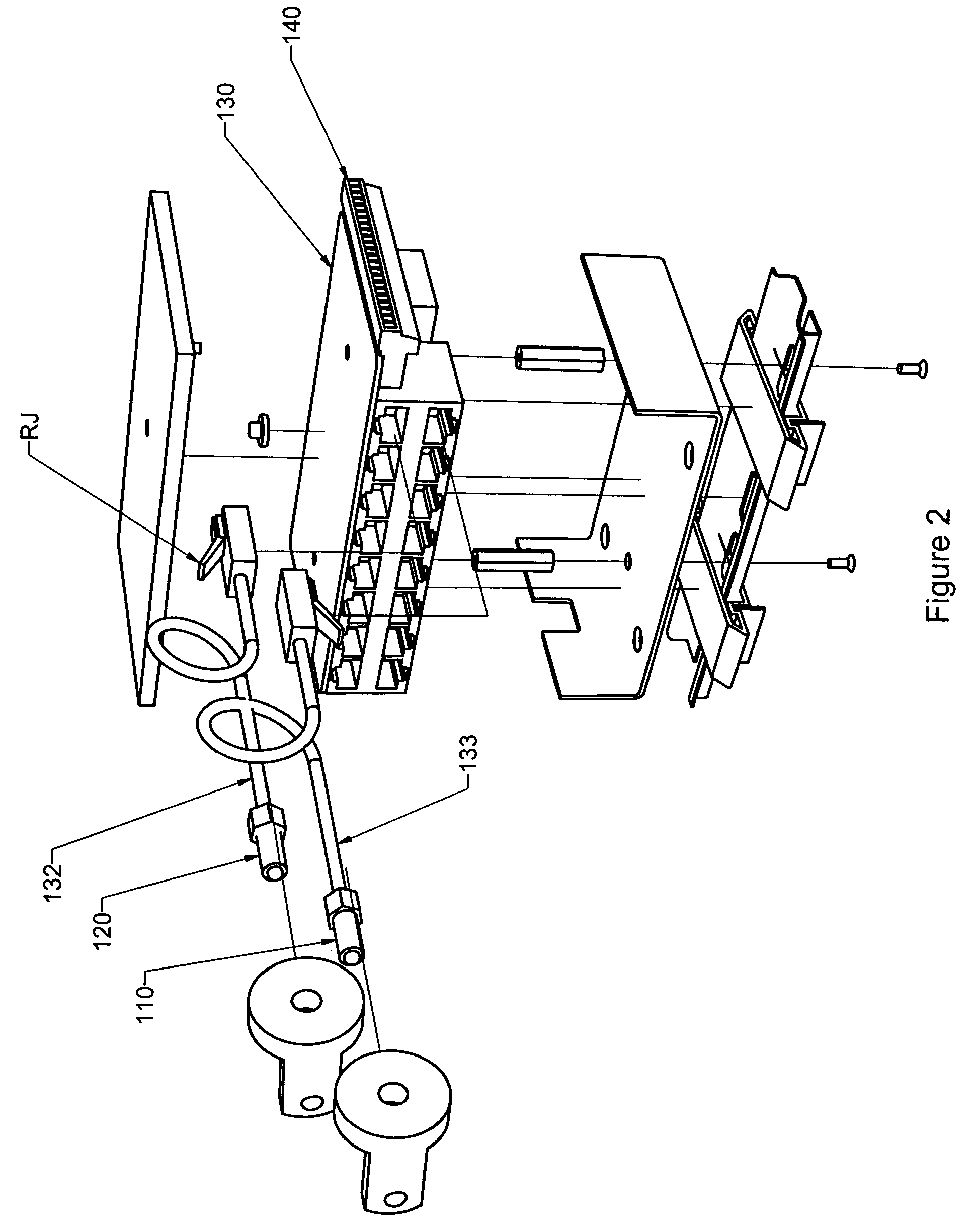
[0037]Referring now to FIGS. 1 and 2, a Flexible Scanning and Sensing Platform (FLEXI) in accordance with one embodiment of the present invention is generally shown as 100. The platform 100 includes remote receiver units 110 and remote transmitter units 120 in cooperation with a controller 130. The remote receiver and transmitter units 110, 120 can, for example, be housed in separate packages, as would be the case for an opposed optical system, or they can be combined in the same housing, as would be the case for proximity inductive or proximity optical systems. The remote rec...


PUM

PropertyMeasurementUnit
Flexibilityaaaaaaaaaa
Sensitivityaaaaaaaaaa
Frequencyaaaaaaaaaa

Abstract

A detection method and apparatus that includes a controller and a plurality of remote sensor units, each containing sensor elements, connected to the controller to achieve custom detection profiles and resolutions that are optimized for a given application by alteration of scanning sequences used by the controller, variation of scanning frequencies, adjustment in response times, and utilization of multi-modal sensing methods.

Description

CROSS REFERENCE TO RELATED DOCUMENTS[0001]This application is related to provisional patent Ser. No. 60 / 402,628 filed on Aug. 12, 2002, entitled “Flexible scanning, sensing platform and a method for direct visual identification of a target location within a beam pattern and system sensitivity control by means of a transmitted signal adjustment” naming Vadim Bondarev and Eric Brooks. The provisional application is hereby incorporated by reference as if disclosed fully herein. Applicants hereby claim priority under 35 U.S.C. 119(e) of this provisional patent application.BACKGROUND OF THE INVENTION[0002]1. Field of the Invention[0003]The present invention pertains to a detection system and method, and more particularly to a flexible platform for scanning and sensing and related method for identification of a target within a detection field.[0004]2. Description of the Related Art[0005]Photoelectric scanners and sensors are widely used in industrial applications for detection, measuremen...

Claims


Application Information

Patent Timeline
IPC IPC(8): G06F11/00G01V3/08G05B24/02G06T7/00
CPCG01V8/20
Inventor BONDAREV, VADIMBROOKS, ERIC R.
Owner SYST TO ASIC
Learn More