
Method of producing forged part and method of producing suspension arm for automotive vehicles

a technology of automotive vehicles and suspension arms, which is applied in the direction of engine components, mechanical equipment, metal-working equipment, etc., can solve the problems of long manufacturing time per product, reduced production efficiency, and long processing time, so as to reduce manufacturing time, efficiently finish a product, and efficiently finish the effect of the produ

Active Publication Date: 2007-08-07
NISSAN MOTOR CO LTD +1
View PDF8 Cites 5 Cited by
  • Summary
  • Abstract
  • Description
  • Claims
  • Application Information

AI Technical Summary

Benefits of technology

The present invention provides a method of manufacturing a forged part that can efficiently finish a product while achieving a reduced manufacturing time. This is achieved by holding a material by a jig, upsetting the material to a first predetermined shape, forging the material into a second predetermined shape, and finish-machining the forged material to remove burrs generated on an outer periphery of the material. The direction in which the material is forged is set so that burrs generated by the upsetting operation are included in burrs generated by the forging operation. This method can also be used to produce an automotive suspension arm by holding a bar-shaped material, upsetting it to a first predetermined shape, forging it into a second predetermined shape, and finish-machining it to remove burrs. The overall efficiency of the manufacturing process is improved.

Problems solved by technology

According to the manufacturing method disclosed in JP8-39183, however, a bar-shaped member is worked to predetermined length and thickness in the roll-forming process, so that a long processing time is required and that a manufacturing time per product becomes long.
Thus, there is a problem of reduced production efficiency.

Method used


Image

  • Method of producing forged part and method of producing suspension arm for automotive vehicles
  • Method of producing forged part and method of producing suspension arm for automotive vehicles
  • Method of producing forged part and method of producing suspension arm for automotive vehicles

Examples


Embodiment Construction

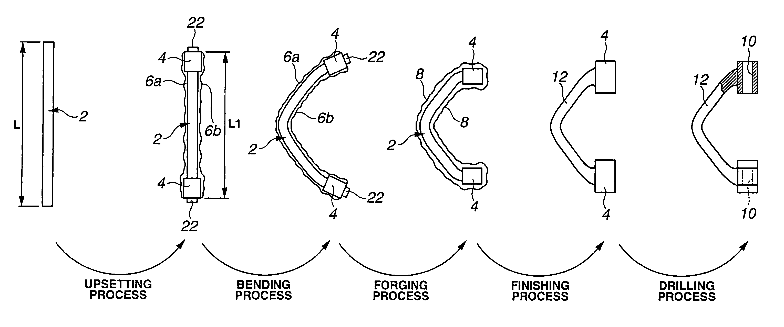
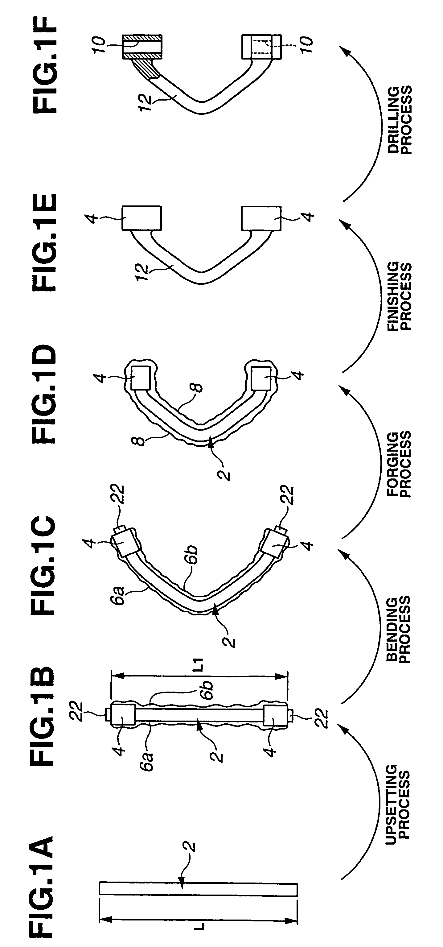
[0017]Referring now to the drawings, particularly to FIGS. 1A-1F, there are shown the explanatory views illustrating a series of automotive suspension-arm manufacturing processes of the embodiment, that is, an upsetting process, a bending process, a forging process, a finish-machining process (simply, a finishing process), and a drilling process.

[0018]FIG. 1A shows a raw material 2 in the form of a round bar initially set to a predetermined length (an initial length) L. FIG. 1B shows the raw material 2 compressed or pressed by upsetting to have a predetermined length L1 (L14, 4. Here, a pair of longitudinally-extending burred portions formed on the outer periphery of raw material 2 and continuously extending in the longitudinal direction of raw material 2 and denoted by reference numerals 6a, 6b are whisker-shaped burrs generated by the upsetting process. FIG. 1C shows the raw material 2 after being bent by bending from a state shown in FIG. 1B. FIG. 1D shows the raw material 2 afte...


PUM

PropertyMeasurementUnit
shapeaaaaaaaaaa
diameteraaaaaaaaaa
lengthaaaaaaaaaa

Abstract

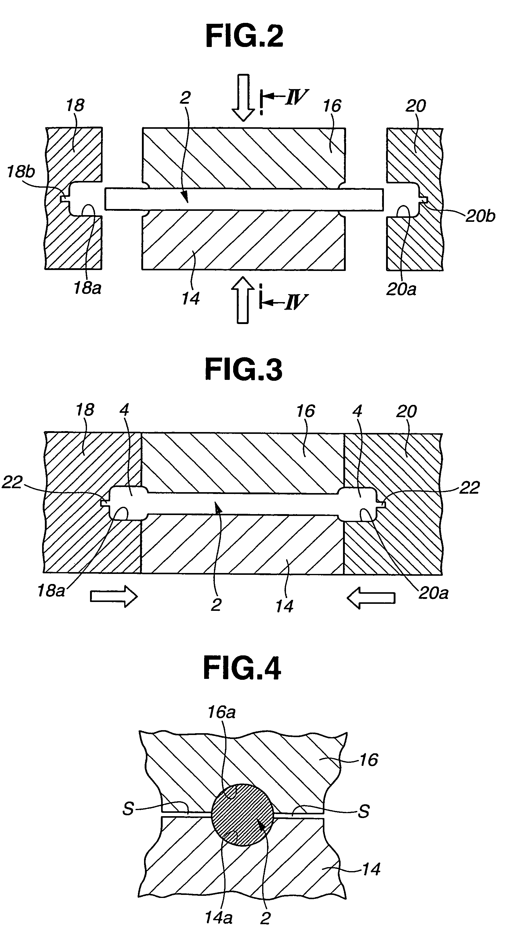
A method of producing a forged part includes holding a material by a jig, upsetting the material, held by the jig, to a predetermined length by a pair of upsetting dies disposed on both ends of the material, while pressing the upsetting dies on the material, so as to produce large-diameter portions at the respective axial ends of the material. Next, a bending operation and a forging operation are made to the upset material, in that order. When forging, a direction, in which the material is forged, is set, so that a burr generated on the material by upsetting is included in a burr generated on the material by forging. Next, a finish-machining operation is made to the forged material to remove the burr left on the outer periphery of the material after forging. Thereafter, the finish-machined material is drilled to form bush-mounting holes in the large-diameter portions.

Description

TECHNICAL FIELD[0001]The present invention relates to a method of producing a forged part and a method of producing a suspension arm for automotive vehicles.BACKGROUND ART[0002]In recent years, there have been proposed and developed various methods of producing a forged part such as a suspension arm for automotive vehicles. One such producing method of a forged part such as an automotive suspension arm has been disclosed in Japanese Patent Provisional Publication No. 08-39183 (hereinafter is referred to as “JP8-39183”). JP8-39183 relates to a manufacturing method including a roll-forming a bar-shaped member to predetermined length and thickness, a compression-forming the roll-formed member, a bending and rough-molding process of rough-molding the compression-formed member while bending the same, a finish-molding process of closed-die-forging (simply, close-forging) the rough-molded member to finish-mold the same, and a drilling process of drilling the finish-molded member. In the ma...

Claims


Application Information

Patent Timeline
Patent Type & Authority Patents(United States)
IPC IPC(8): B21J5/08
CPCB21J5/00B21J5/02B21J5/08B21K1/06B21K1/74
Inventor SAKURAGI, HIDEYORIKONNO, YOSHIHIROKAWAI, HIDENOBU
Owner NISSAN MOTOR CO LTD
Learn More