Electrical connector

a technology of electrical connectors and connectors, applied in the direction of coupling device connections, inductances, garments, etc., can solve the problems of reducing the lifespan of connectors and/or equipment, affecting the service life of connectors, and affecting the service life of equipment, so as to achieve the effect of rapid and precise opening and closing of connectors

Inactive Publication Date: 2007-08-07
THALES HLDG UK
View PDF11 Cites 38 Cited by
  • Summary
  • Abstract
  • Description
  • Claims
  • Application Information

AI Technical Summary

Benefits of technology

[0023]An advantage of the present invention is that it incorporates the functions of a mechanical connection and an electrical connection in a single connector, thereby removing the need for a separate strap connector (for mechanical strength) and wire connector (for electrical connection).
[0024]The inventors of the present invention have surprisingly found that contact-less electrical connectors can be employed in harsh outdoor environments where repeated opening and closing of the connector is required and where the connector is to form a mechanical connection for equipment carried by an individual. This is surprising because known contact-less connectors are of a size and design that is quite inappropriate to be carried or worn by an individual in these environments. Furthermore, known contact-less connectors do not provide both strong mechanical connection and the ability to rapidly and precisely open and close the connector by hand. What is more, known contact-less connectors would be susceptible to the ingress of dirt, dust and liquid if they were to be opened and closed repeatedly in the type of environments discussed above.
[0025]Preferably the primary and secondary coupling elements overlap and provide an electromagnetic connection along at least one of the socket walls. This arrangement has the advantage that any dirt or dust which is introduced into the socket will be less likely to interfere with the coupling than would be the case were the coupling elements to be located in the base of the socket portion and the tip of the tongue respectively because dirt and dust will tend to aggregate at the base of the socket, due to the action of the tongue repeatedly entering the socket.
[0026]Therefore the present invention addresses both known and previously unrecognised drawbacks associated with conventional direct contact conductive connectors and employs technology based on contact-less electrical connectors. At its broadest the present invention provides a two-part contact-less electrical connector which may be carried or worn by an individual such as a soldier for transmitting data and / or power in harsh outdoor environments and in particular a battlefield environment where dust and dirt may be a problem.
[0027]Preferably the primary and secondary coupling elements overlap when the tongue is engaged in the socket and this overlap enables electromagnetic coupling to occur. The coupling elements may for example be inductor or capacitor structures and so the overlap between the coupling elements may be regarded as a magnetic flux overlap or a dielectric charge overlap respectively.
[0028]Data and / or power may be transmitted through the connector in either or both directions.

Problems solved by technology

Firstly, repeated opening and closing of any direct contact electrical connector will inevitably involve wear and tear of the contact surfaces, especially if significant power is passing through the connector at the time the connector is disconnected since this may cause arcing and oxidation at the contact surface.
This results in degraded performance over time and can reduce the lifespan of the connector and / or equipment and increase maintenance costs.
Secondly, when electrical connectors are opened and closed in these environments there will inevitably be some dirt, dust or liquid that contaminates one or both halves of the connector.
In a simple direct contact conductive connector, any dust or dirt on the contact surfaces will reduce the efficiency of the electrical connection with the result that the equipment may function incorrectly, inefficiently or not at all.
Conventional connectors do not cope well in the environments experienced by soldiers, in particular immersion in salt water, the ingress of sand and exposure to chemical warfare agents.

Method used


Image

  • Electrical connector
  • Electrical connector
  • Electrical connector

Examples


Embodiment Construction

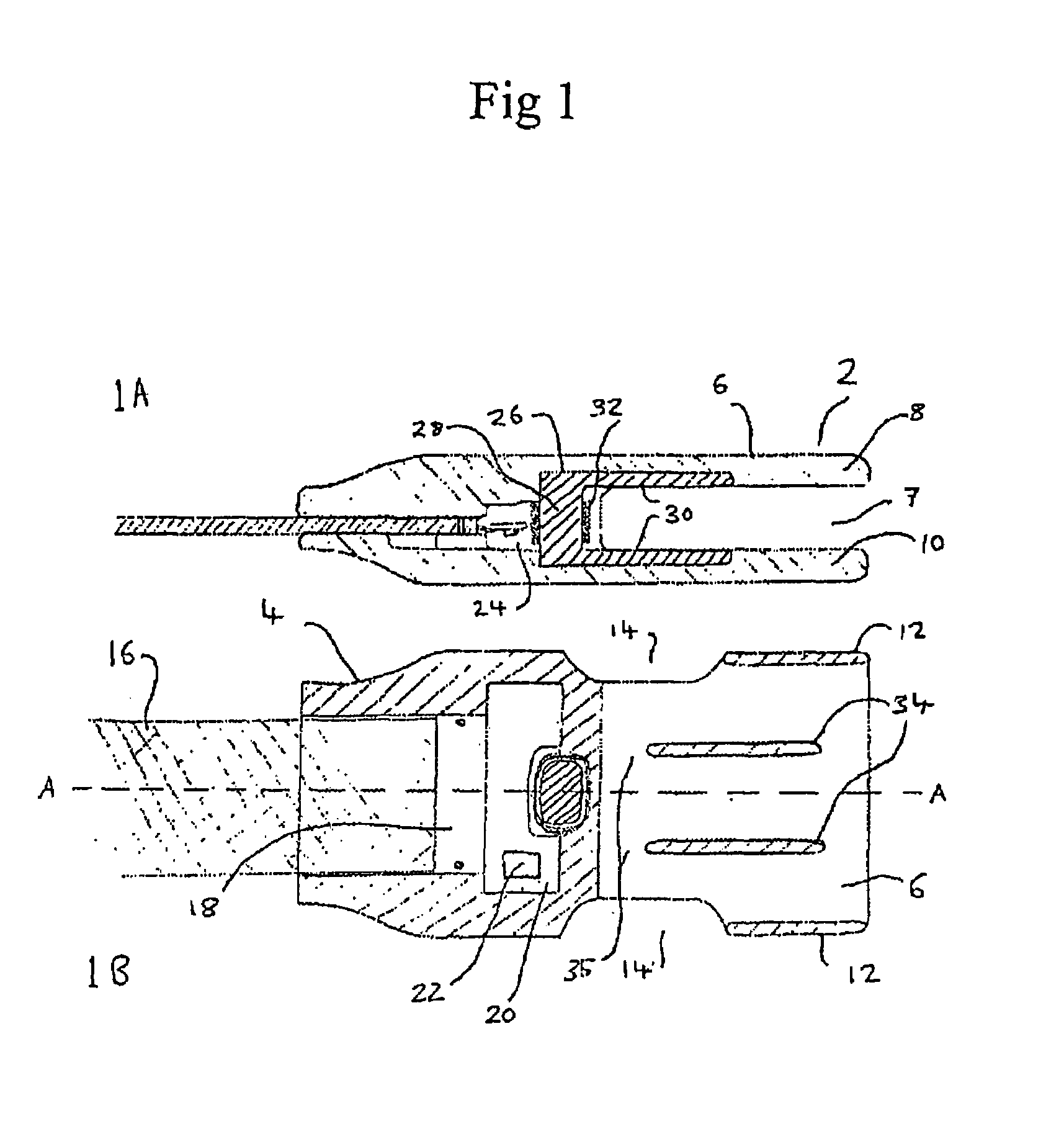
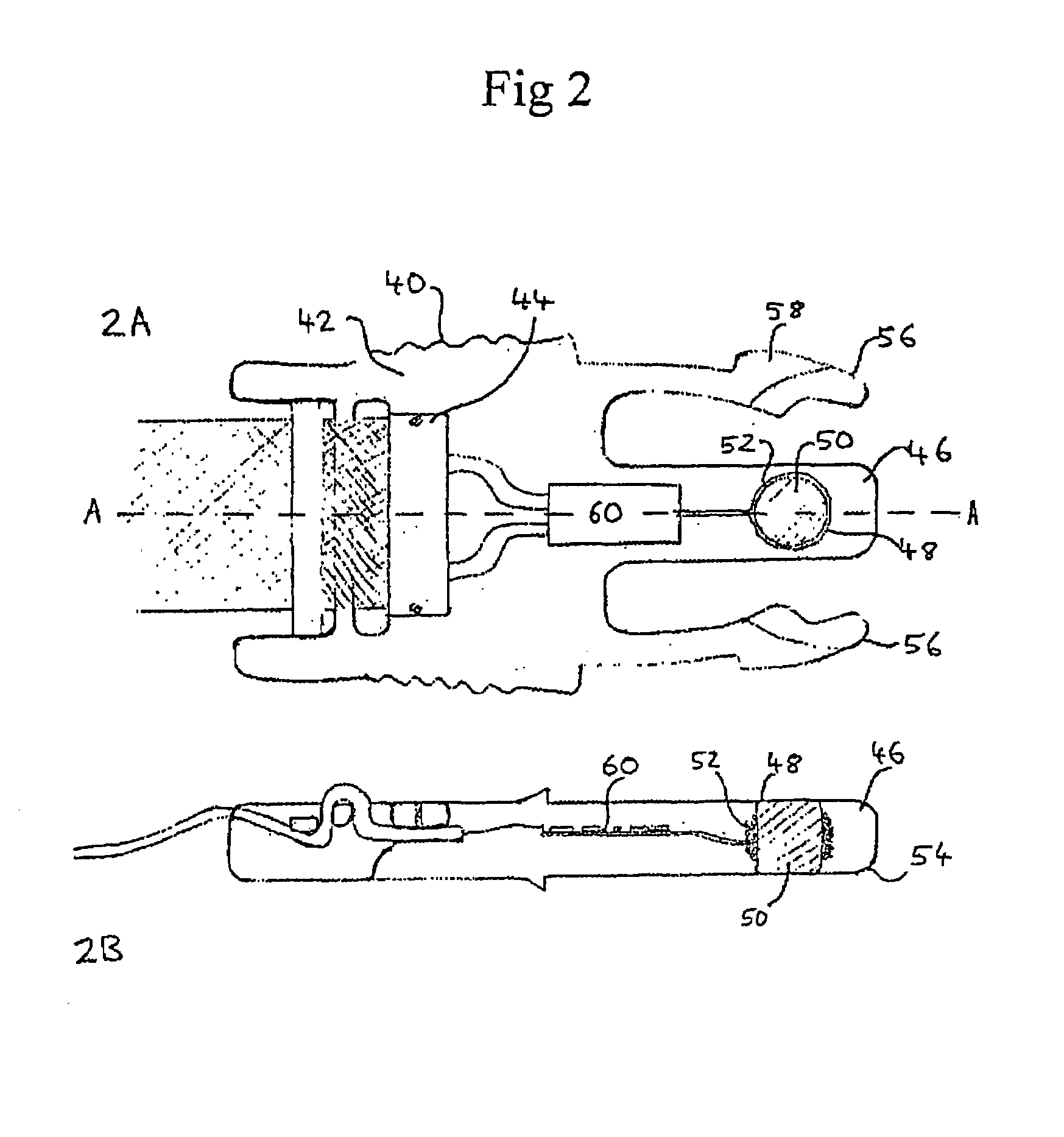
[0093]FIG. 1 shows the socket portion 2 of a contact-less connector of the present invention. The connector has a structure similar to that of a squeeze-to-release clip or buckle commonly found on rucksacks (see tongue portion 40 in FIG. 2). The socket portion has a base 4 and walls 6 extending from the base to define a socket 7. The socket portion has a flat profile that makes it more comfortable when worn or carried by an individual. The socket walls include opposing upper 8 and lower 10 walls that extend from the base and two opposing side walls 12 which extend from the mouth of the socket to about midway along the length of the socket. This arrangement provides a gap 14 in each side of the socket between the base 4 and side walls 12. These gaps act as detents that co-operate with latches 56 on the tongue portion (see FIG. 2). The detents may also, for example, be provided by apertures or openings in the socket walls or, for example, depressions in or projections on a surface of ...


PUM

PropertyMeasurementUnit
frequenciesaaaaaaaaaa
frequencyaaaaaaaaaa

Abstract

The present invention may provide a two-part electrical connector havinga first part being a tongue portion having a base and a tongue extending longitudinally therefrom;a second part being a socket portion having a base and walls extending therefrom defining a socket for slidably receiving the tongue, the tongue portion and socket portion having locking means to permit releasable mutual engagement, said locking means including a locking member moveable between a first position in which the tongue is held in the socket and a second position in which the tongue is removable from the socket;a primary coupling element located in the tongue; anda secondary coupling element located in at least one of the socket walls, which elements provide a contact-less electromagnetic coupling when the tongue is engaged in the socket.

Description

TECHNICAL FIELD[0001]This invention relates to electrical connectors and in particular contact-less electrical connectors, that is electrical connectors where there is no direct contact between electrical conductors.BACKGROUND OF THE INVENTION[0002]The use of portable or hand-held electrical equipment in harsh outdoor environments and in particular by soldiers in combat environments is becoming commonplace. It is desirable and sometimes essential that such equipment be repeatedly connected and disconnected to a power supply and / or other electrical equipment so that the equipment can perform its function and be stowed when not in use.[0003]Electrical connectors currently used in combat environments employ direct electrical contacts and a sealing mechanism to protect the connector. Typically, the sealed connectors are circular and use a threaded connection. Examples of these sorts of connectors are MIL-STD-1760 and MIL-STD-38999 connectors.[0004]In contrast to these direct contact con...

Claims


Application Information

Patent Timeline
Patent Type & Authority Patents(United States)
IPC IPC(8): H01R9/22A41D1/00H01F38/14H01R12/24H01R13/52H01R13/58H01R13/627
CPCH01F38/14A41D1/002H01F2038/146H01R13/5219H01R13/5227H01R13/5833H01R13/6272H01R13/6273H01R23/661Y10S439/95H01R12/772H01G4/40
Inventor HUNTER, ANDREW
Owner THALES HLDG UK
Why Eureka
Try Eureka