Door obstacle sensor

a door and obstacle technology, applied in the direction of optical radiation measurement, counting objects on conveyors, instruments, etc., can solve the problems of failure to receive and obstruction of entranceways, and achieve the effect of preventing false triggering

Inactive Publication Date: 2007-08-07
MIREMADI REZA
View PDF5 Cites 10 Cited by
  • Summary
  • Abstract
  • Description
  • Claims
  • Application Information

AI Technical Summary

Benefits of technology

[0009]Another object of this invention is to provide an arrangement that reliably detects objects, such as persons and / or things, in an area, such as an entranceway.
[0013]Thus, in accordance with this invention, the transmitter, the receiver and the controller are all mounted at one side of the entranceway, while the retroreflector, which does not require electrical power or wiring, is mounted at the opposite side of the entranceway. The measurement of arrival time of light and the processing of differences in arrival times, within predefined safety margins, prevents false triggering on obstacles at close range.

Problems solved by technology

However, failure to receive the light beam indicates that the entranceway has an obstruction.
One limitation of such folded path systems is that when an obstruction 5 is relatively near the receiver 2, the power level reflected by the obstruction 5 can be the same as the power level reflected by the retroreflector 4.
However, even a polarizer can be tricked by a diffused reflective object at close range.

Method used


Image

  • Door obstacle sensor
  • Door obstacle sensor
  • Door obstacle sensor

Examples


Embodiment Construction

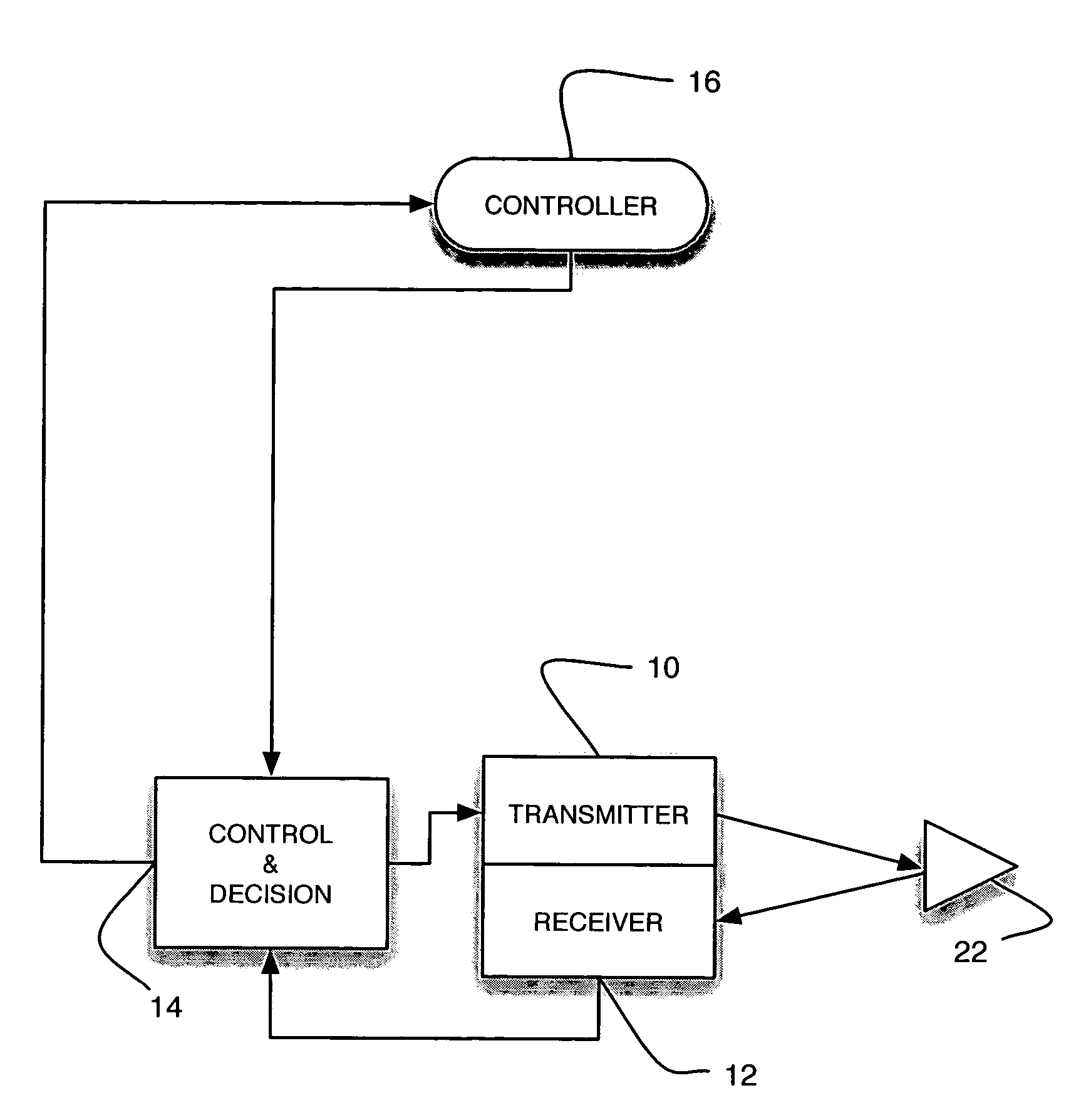
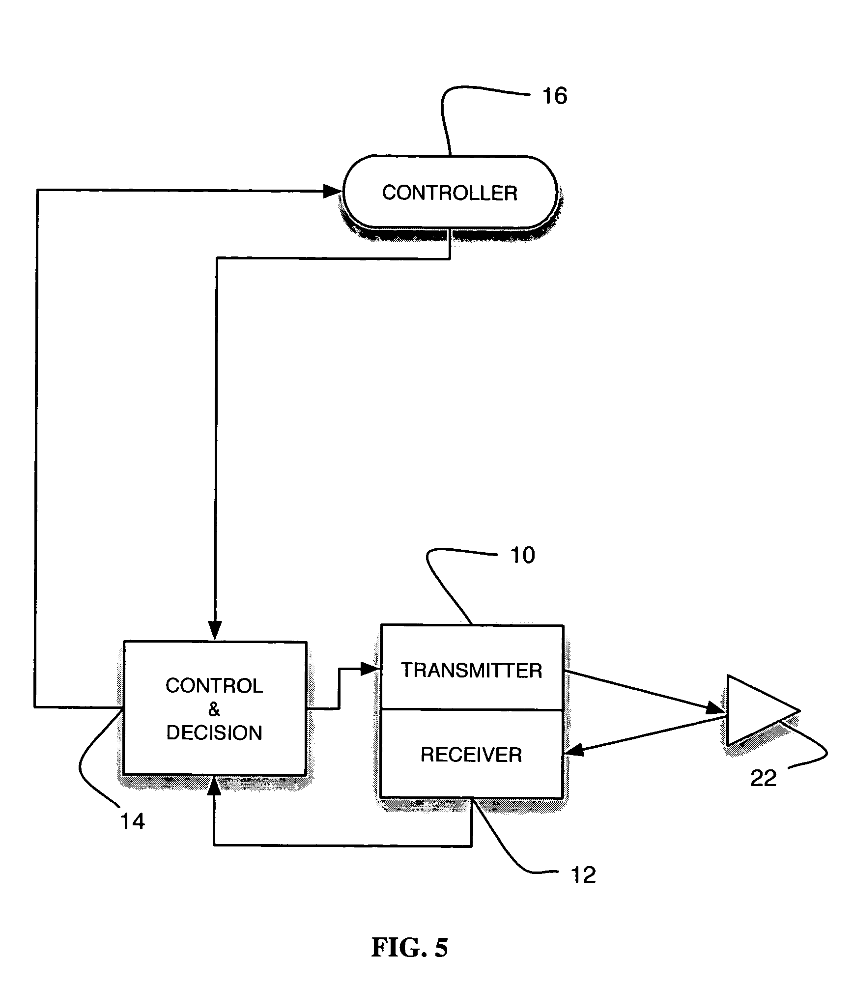
[0026]Referring now to FIG. 5 of the drawings, reference numeral 10 generally identifies a transmitter positioned adjacent a receiver 12, and both connected to an electrical circuit including a control and decision section 14 which, in turn, is connected to a controller 16. The transmitter 10, receiver 12, and control circuitry 14 are all mounted, in a preferred embodiment, in a housing 18 (see FIG. 6) at one side wall of an entranceway, access to which is controlled by a controller 16 that moves a garage door 20. A retroreflector 22 is mounted at the opposite side wall of the entranceway. The term “wall” as used herein is intended to cover any form of support, including a fence or stakes on either side of a driveway.

[0027]As shown in FIG. 7, reference numeral 24 identifies a light emitting diode, preferably at a frequency of 850 nm, for emitting light to a target 26 for reflection therefrom. A photodiode 28 has a field of view and detects the reflected light and generates electrica...


PUM


Abstract

A door obstacle sensor in which an optical transmitter and a receiver are located on the same side of an entranceway, and a retroreflector is placed on the opposite side. A controller measures the time of flight of a light beam that is reflected from the retroreflective target. All future target distances are compared to the initial distance, and a decision is made as to an object being present in or absent from the entranceway.

Description

BACKGROUND OF THE INVENTION[0001]1. Field of the Invention[0002]This invention generally relates to an arrangement for, and a method of, detecting the presence or absence of persons or things in an area, such as an entranceway, both outdoor and indoor, and, more particularly, to fail-safe obstruction detectors especially useful in systems for controlling garage doors, elevator doors and the like, and to security systems for controlling access to a secure area.[0003]2. Description of the Related Art[0004]An obstruction detector for an automatic garage or elevator door control system prevents personal injury and / or property damage to a person or thing caught in the closing door, as well as preventing damage to the door itself and the various drive components that close the door.[0005]As shown in FIGS. 1-2, it has been proposed to use a light transmitter 1 powered by a controller 7 to transmit a light beam, along a direct path, across a door opening or entranceway for detection by a li...

Claims


Application Information

Patent Timeline
Patent Type & Authority Patents(United States)
IPC IPC(8): G01J1/00G01J1/36G01V8/14
CPCG01V8/14
Inventor MIREMADI, REZA
Owner MIREMADI REZA
Why Eureka
Try Eureka