
Radiological imagery method and device

a radiological imaging and method technology, applied in the direction of x-ray apparatus, radiation intensity measurement, electrical apparatus, etc., can solve the problems of inability to achieve the effect of x-ray imaging in industrial level, slow image acquisition speed of detectors, and insufficient global output, so as to reduce notably the dose d of x-ray photons, the effect of simple design and operation mod

Inactive Publication Date: 2007-08-07
UNIV PIERRE & MARIE CURIE
View PDF12 Cites 0 Cited by
  • Summary
  • Abstract
  • Description
  • Claims
  • Application Information

AI Technical Summary

Benefits of technology

[0011]The aim of this invention is to suggest a method and a radiological measuring device simple in their design and in their operating mode, rapid and economical, enabling to reduce notably the dose D of X-ray photons received by a patient during a radiological test.
[0013]It is then possible to expose the subject to a flux cumulated in the time shorter than that necessary with the conventional devices fitted with slow detectors requiring a long duration excitation signal, while using possibly greater flux F. The advantages of such a method are that in integration measuring mode, the noise of the detector (black current) is integrated over a time tp shorter than Te and the signal / noise ratio is thereby increased. Finally, it enables another measuring mode of the signal, i.e. measuring the intensity of the current delivered by the detector subjected to the flux F. Excitation signal, luminous flux or X-ray are used here indifferently to designate the flux of photons to which is exposed the subject or the organ that one wishes to visualise.

Problems solved by technology

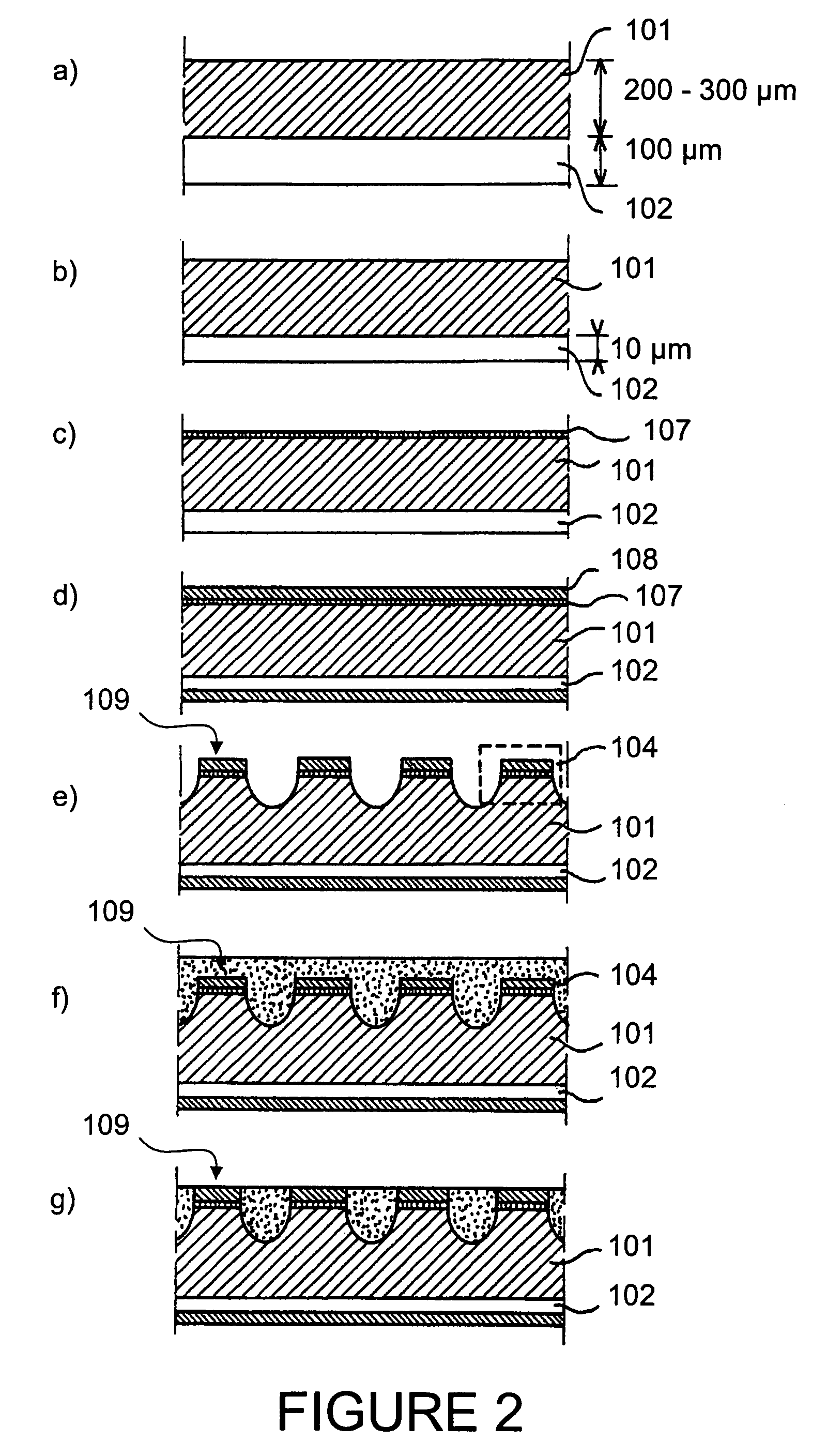
But because of the small size of the crystals available and the absence of microelectronic technology, the implementation of this material to perform X-ray imaging is not possible at industrial level.
Their global output is however not optimum.
These detectors still have an image acquisition speed which is slow (of the order of several seconds due to the response time of the scintillator).

Method used


Image

  • Radiological imagery method and device
  • Radiological imagery method and device
  • Radiological imagery method and device

Examples


Embodiment Construction

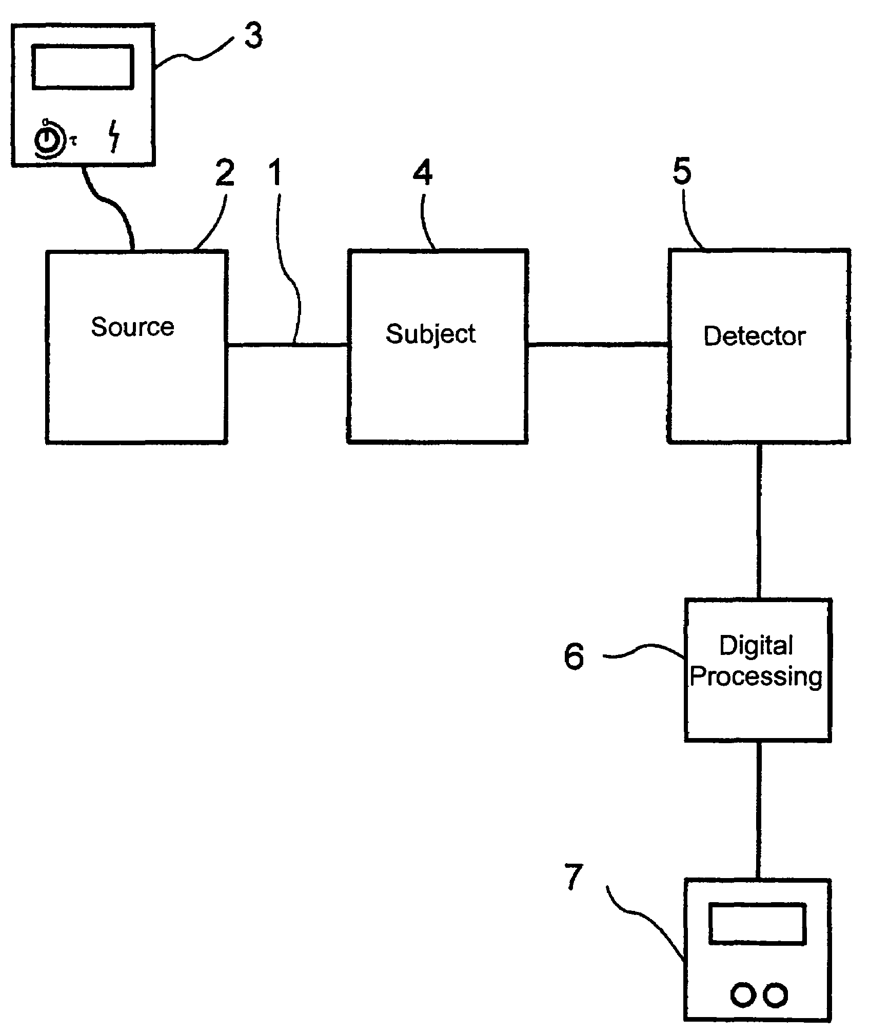
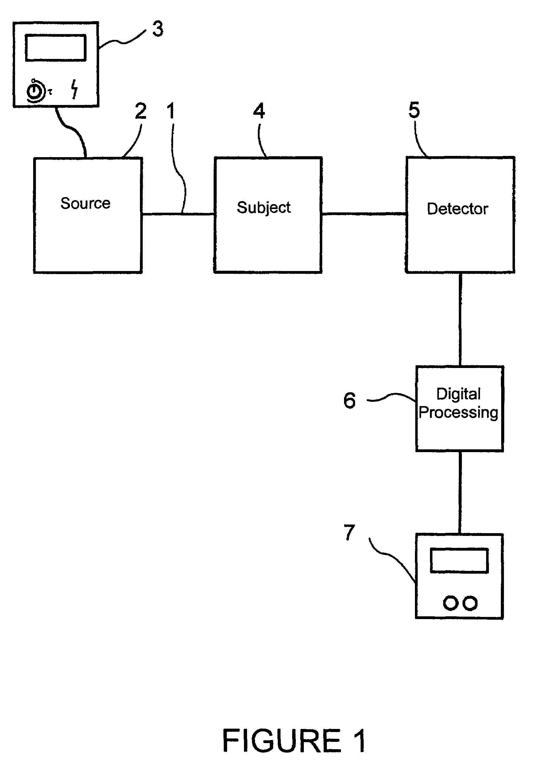
[0045]The instant signal S generated by a current detector under a flux F of X-ray photons is weak and of continuous type at a few ms-scale. This signal S is therefore difficult to extract from the background noise measured by the detector, itself continuous at this time scale. In order to obtain a response R of the detector which is significant and processable, the signal S should be integrated for an exposure time Te sufficient to imply that the patient receives, during the acquisition of this response R, the dose D=F×Te. The aim of the present invention is to replace the response R of the detector with a pulse signal. By measuring the instant signal Si for a short duration Ti before Te, with a flux of photons Fi, and in sensing said signal Si with an X-ray detector having very quick response time tr, the dose may then be reduced. Indeed, one switches thus from the dose D to a dose Di=Fi×Ti where Ti / Te is smaller than Fi / Fe so that Di is shorter than D. Fi may be greater than F bu...


PUM


Abstract

The relation relates to a method and a radiological imaging device. A subject (4) is illuminated by a luminous flux (1) generated by an X-ray source (2). This luminous flux (1) is a pulse having a duration tp shorter than 1 ms. The signals S derived from the interaction of the luminous flux (1) with the subject (4) are then detected by means of an X-ray detector (5) having a response time tr shorter than 0.1 ms.Applications possible in medical imaging (mammography, dental care, . . . ).

Description

CROSS-REFERENCE TO RELATED APPLICATION[0001]This application is a National Stage entry of International Application No. PCT / FR02 / 03904, filed Nov. 14, 2002, the entire specification claims and drawings of which are incorporated herewith by reference.BACKGROUND OF THE INVENTION[0002]1. Field of the Invention[0003]This invention relates to a method and a radiological imaging device.[0004]Since its first use at the beginning of the 20th century, radiography has vastly transformed and simplified the diagnostic of numerous diseases. This technique is based upon the absorption, by the organ examined, of a portion of the X-rays emited by a source and the impression of the complementary X-rays having traversed the organ in question, on a screen sensitive to the latter. A negative image of the organ examined is thus obtained. Although other imaging techniques (nuclear magnetic resonance (NMR), Echography, . . . ) have appeared more recently, this conventional radiology still represents a ver...

Claims


Application Information

Patent Timeline
Patent Type & Authority Patents(United States)
IPC IPC(8): H05G1/64G01T1/24
CPCG01T1/24
Inventor BOURGOIN, JACQUES
Owner UNIV PIERRE & MARIE CURIE
Learn More