
Impedance matched waterproof connector for CATV filter housing

Active Publication Date: 2007-08-14
PPC BROADBAND INC
View PDF12 Cites 10 Cited by
  • Summary
  • Abstract
  • Description
  • Claims
  • Application Information

AI Technical Summary

Benefits of technology

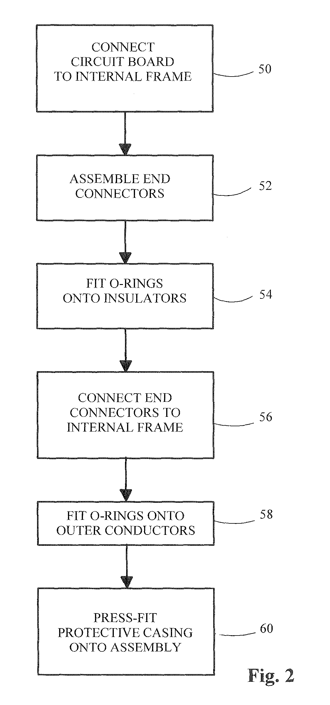
[0009]Briefly stated, an RF filter which includes a circuit board connected to an internal frame has two end connectors connected to the frame, with a protective casing connected to the internal frame and the end connectors. Insulators in each end connector are shaped to form air pockets between the air pockets and the outer conductor portion of the end connectors. A plurality of O-rings are disposed in various locations on the insulators to prevent moisture from entering the filter. The RF filter passes the SCTE Red Dye Test and limits return loss to better than negative 20 dB.
[0010]According to an embodiment of the invention, an RF filter includes a circuit board connected to an internal frame; first and second end connectors connected to the frame; a protective casing connected to the internal frame and the first and second end connectors; the first end connector including a first outer conductor and containing a first inner conductor and a first insulator, wherein the first insulator is effective for creating a first air pocket between the first insulator and the first outer conductor; and the second end connector including a second outer conductor and containing a second inner conductor and a second insulator, wherein the second insulator is effective for creating a second air pocket between a portion of the second insulator a

Problems solved by technology

While these materials typically are very good at preventing moisture from entering the device housing, they create very low impedance zones within the connections which are not matched to the 75 ohm impedance of the CATV system.
While this does not prevent signal transmission to a debilitating degree in analog systems, it does cause a great deal of signal reflection, i.e., high return loss, which can cause debilitating interference in systems which operate digital programming and data within their bandwidth.
While some of this reflection may be compensated for by selective tuning of the filter circuit within the housing, it is not sufficient if return loss values of −20 dB or less, i.e., −30 dB, −40 dB, etc., are desired.

Method used


Image

  • Impedance matched waterproof connector for CATV filter housing
  • Impedance matched waterproof connector for CATV filter housing
  • Impedance matched waterproof connector for CATV filter housing

Examples


Embodiment Construction

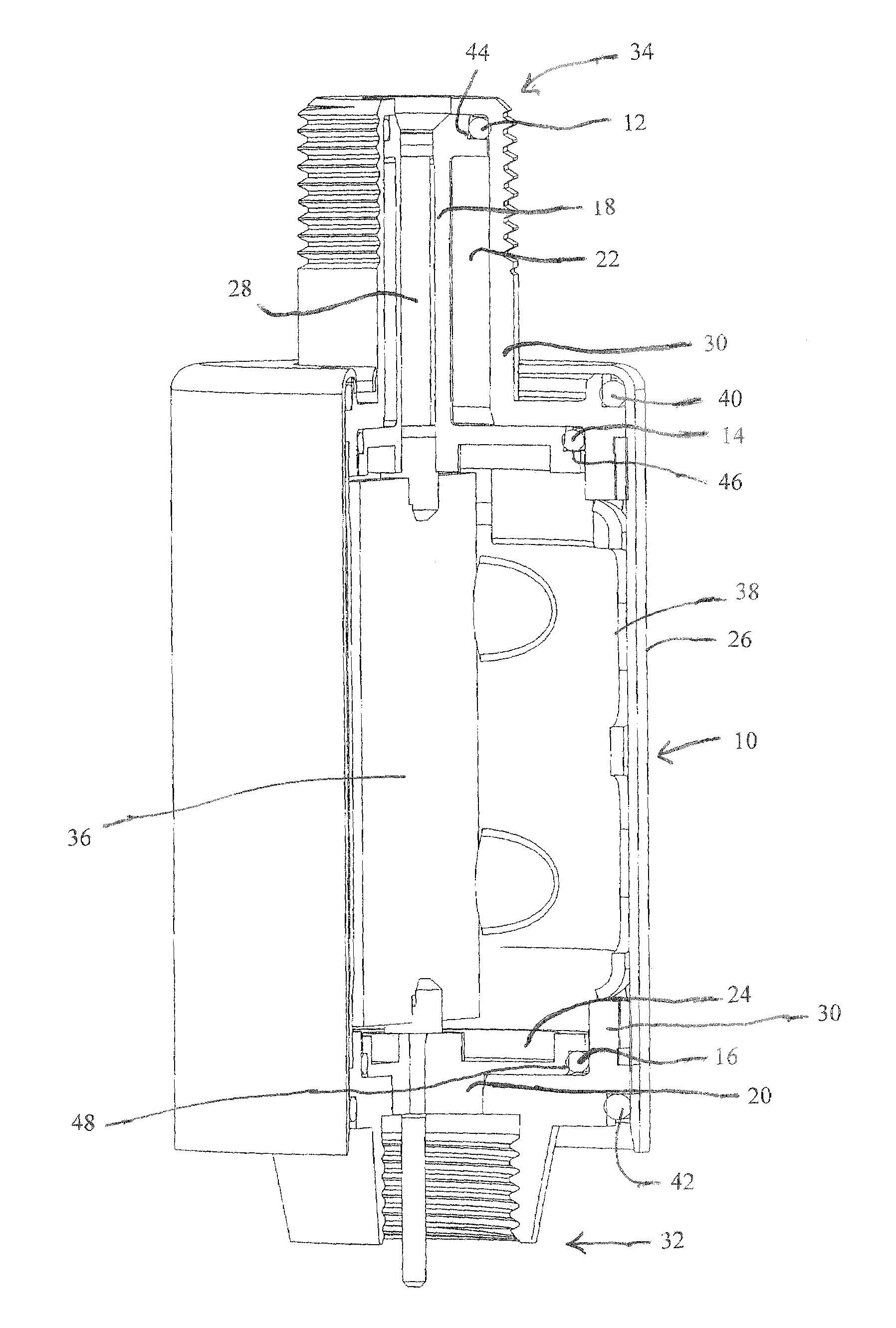
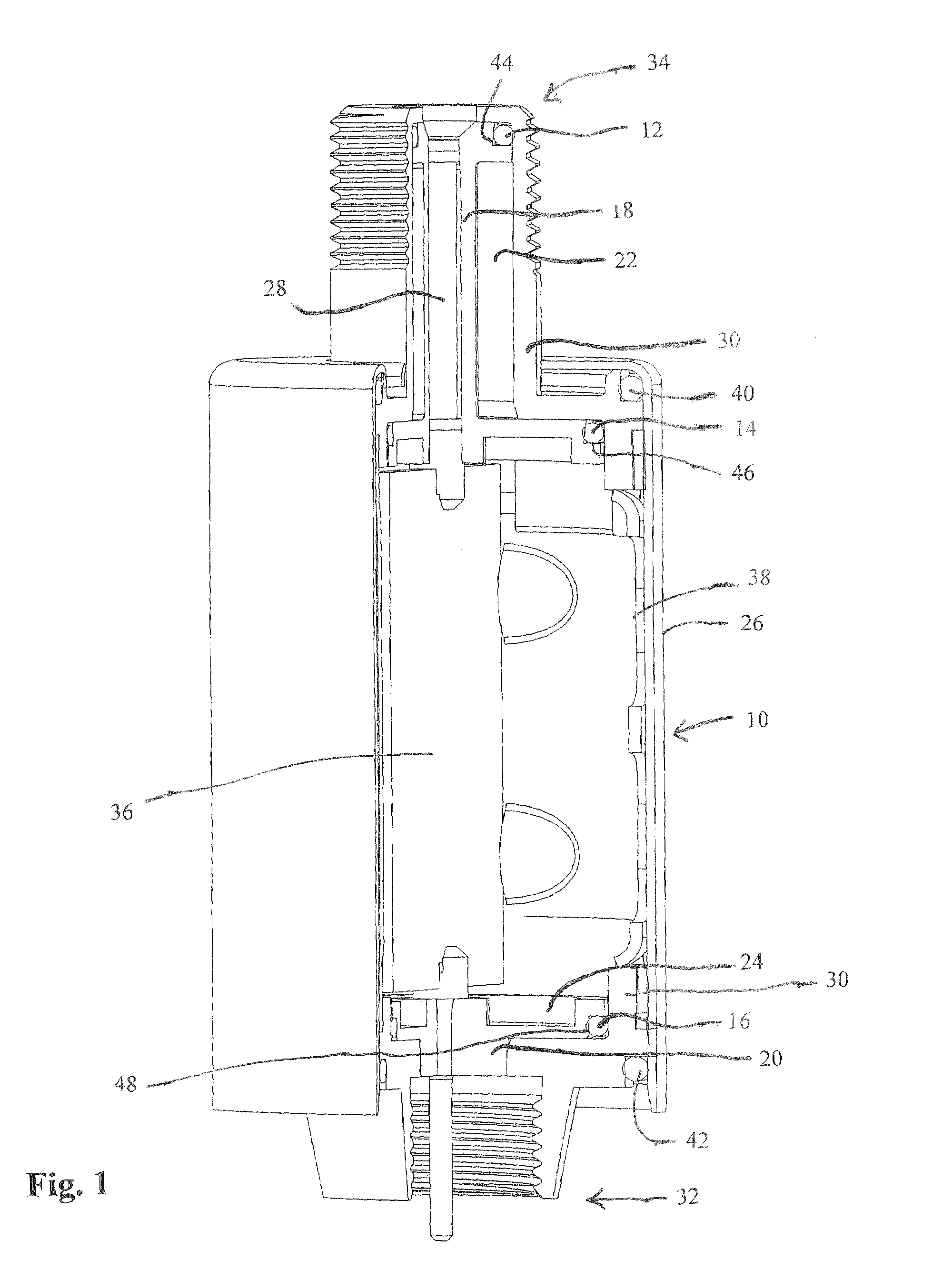
[0014]Referring to FIG. 1, a filter 10 includes a circuit board 36 connected to an internal frame 38. Circuit board 36 contains the electronic portions of filter 10 which typically pass frequencies within one or more specified bandwidths while blocking frequencies of other bandwidths. Internal frame 38 and circuit board 36 are preferably contained within a protective casing 26. An end connector 32 of filter 10 connects to an RF port, while an end connector 34 connects to a coaxial cable. End connectors 32, 34 include an inner conductor an inner conductor 28 and an outer conductor 30, which is usually grounded.

[0015]At end 34 of filter 10, an insulator 18 is shaped to create an air pocket 22, while at end connector 32, an insulator 20 is shaped to create an air pocket 24. Insulators 18 and 20 are preferably rigid engineering thermopolymers, and the combination of insulators 18, 20 with air pockets 22, 24 permits better impedance matching compared to the prior art.

[0016]Because insula...


PUM


Abstract

An RF filter which includes a circuit board connected to an internal frame has two end connectors connected to the frame, with a protective casing connected to the internal frame and the end connectors. Insulators in each end connector are shaped to form air pockets between the air pockets and the outer conductor portion of the end connectors. A plurality of O-rings are disposed in various locations on the insulators to prevent moisture from entering the filter. The RF filter passes the SCTE Red Dye Test and limits return loss to better than negative 20 dB.

Description

FIELD OF THE INVENTION[0001]This invention relates generally to the field of filter housings used in CATV systems, and more particularly to impedance matched waterproof connectors used in such a filter housing.BACKGROUND OF THE INVENTION[0002]It has been the custom for many years in the CATV trap and filter industry to focus upon the hermesticity of the device housing when designing the connectors at each end of the housing. This has led to a preference for moisture blocking insulative materials such as glass and thick cross-section pieces of rubber. While these materials typically are very good at preventing moisture from entering the device housing, they create very low impedance zones within the connections which are not matched to the 75 ohm impedance of the CATV system.[0003]While this does not prevent signal transmission to a debilitating degree in analog systems, it does cause a great deal of signal reflection, i.e., high return loss, which can cause debilitating interference...

Claims


Application Information

Patent Timeline
IPC IPC(8): H01R9/05
CPCH01R13/52H01R24/44H01R13/5202H01R13/521H01R13/5213H01R13/6658H01R2103/00H04N7/102
Inventor CHAWGO, SHAWNMONTENA, NOAH
Owner PPC BROADBAND INC
Learn More