Lithographic apparatus and method for calibrating the same

a technology of lithographic apparatus and calibrating method, which is applied in the direction of printers, dynamo-electric machines, instruments, etc., can solve the problem of expensive position detector

Active Publication Date: 2007-08-14
ASML NETHERLANDS BV
View PDF10 Cites 145 Cited by
  • Summary
  • Abstract
  • Description
  • Claims
  • Application Information

AI Technical Summary

Problems solved by technology

A disadvantage of the interferometers however is that it is an expensive position detector.

Method used


Image

  • Lithographic apparatus and method for calibrating the same
  • Lithographic apparatus and method for calibrating the same
  • Lithographic apparatus and method for calibrating the same

Examples


Embodiment Construction

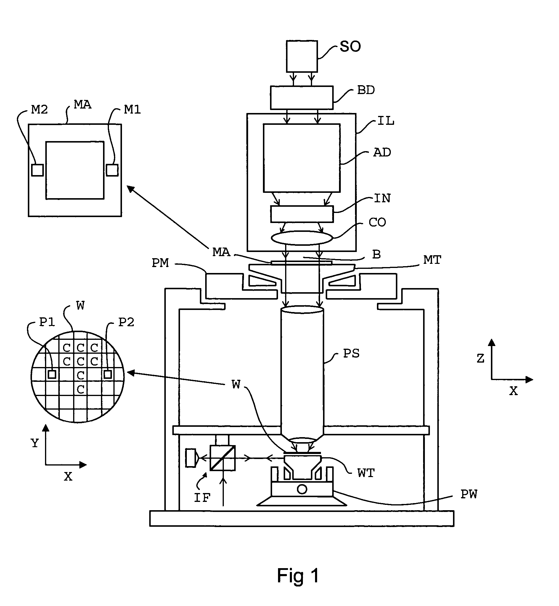
[0021]FIG. 1 schematically depicts a lithographic apparatus 1 according to an embodiment of the invention. The apparatus 1 comprises:

[0022]an illumination system (illuminator) IL: for providing a radiation beam B of radiation (e.g., UV or EUV radiation).

[0023]a first support structure (e.g., a mask table / holder) MT: for supporting patterning device (e.g., a mask) MA and coupled to first positioning mechanism PM for accurately positioning the patterning device with respect to item PS;

[0024]a substrate table (e.g., a wafer table / holder) WT: for holding a substrate (e.g., a resist-coated wafer) W and coupled to second positioning mechanism PW for accurately positioning the substrate with respect to item PS; and

[0025]a projection system (e.g., a reflective projection lens) PS: for imaging a pattern imparted to the radiation beam B by patterning device MA onto a target portion C (e.g., comprising one or more dies) of the substrate W.

[0026]As here depicted, the apparatus is of a transmiss...


PUM


Abstract

Lithographic apparatus includes a substrate table and a motion control system for controlling a movement of the substrate table. The motion control system includes at least 3 position detectors constructed for detecting a position of the substrate table. For measuring a position and orientation of the substrate table, each position detector comprises an optical encoder of a single dimensional or multi dimensional type, the optical encoders being arranged for providing together at least 6 position values, at least one position value being provided for each of the 3 dimensions. 3 or more of the at least 3 optical encoders being connected to the substrate table at different locations in the 3 dimensional coordinate system. The motion control system is arranged to calculate the position of the substrate table in the 3 dimensional coordinate system from a subset of at least 3 of the 6 position values and to calculate an orientation of the substrate table with respect to the coordinate system from another subset of at least 3 of the 6 position values. Further, a method for calibrating the position detectors is described.

Description

BACKGROUND OF THE INVENTION[0001]1. Field of the Invention[0002]The present invention relates to a lithographic apparatus and method for calibrating the same.[0003]2. Description of the Related Art[0004]A lithographic apparatus is a machine that applies a desired pattern onto a target portion of a substrate. Lithographic apparatus can be used, for example, in the manufacture of integrated circuits (ICs). In that circumstance, a lithographic patterning device, which is alternatively referred to as a “mask” or “reticle,” may be used to generate a circuit pattern corresponding to an individual layer of the IC, and this pattern can be imaged onto a target portion (e.g., comprising part of, one or several dies) on a substrate (e.g., a silicon wafer) that has a layer of radiation-sensitive material (i.e., resist).[0005]In general, a single substrate will contain a network of adjacent target portions that are successively exposed. Known lithographic apparatus include so-called steppers, in...

Claims


Application Information

Patent Timeline
Patent Type & Authority Patents(United States)
IPC IPC(8): G03B27/58G03B27/32G03B27/42G03B27/52
CPCG03F7/70458G03F7/70516G03F7/70775G03F9/7011G03F9/7019H01L21/0274
Inventor LOOPSTRA, ERIK ROELOFLEVASIER, LEON MARTINOESTERHOLT, RENE
Owner ASML NETHERLANDS BV
Why Eureka
Try Eureka