Fuel assembly and thimble screw of the same

a technology of fuel assembly and thimble screw, which is applied in the direction of nuclear elements, nuclear engineering problems, greenhouse gas reduction, etc., can solve the problem that the control rod may not be inserted well, and achieve the effect of preventing the deformation of the dashpot flexural

Inactive Publication Date: 2007-08-14
MITSUBISHI HEAVY IND LTD
View PDF16 Cites 28 Cited by
  • Summary
  • Abstract
  • Description
  • Claims
  • Application Information

AI Technical Summary

Benefits of technology

[0025]The present invention has been made in view of the above situation, and has as its object to provide a fuel assembly in which an improved guide thimble is employed and the diameter of the drain hole of a thimble screw is adjusted so that a fall impact produced when a control rod falls is moderated, and flexural deformation of a dashpot is prevented, without impairing the cooling function of non fuel bearing components, and a thimble screw of the fuel assembly.
[0028]Hence, the coolant can be sufficiently supplied also from the viewpoint of assuring the cooling function of the non fuel bearing components. From the viewpoint of moderating the fall impact of the control rod as well, the terminal velocity of the control rod can be suppressed to be equal to or less than the fall velocity with which the fall impact of the control rod can be moderated. Therefore, flexural deformation of the dashpot can be prevented.
[0030]More specifically, the thimble screw is disposed in a bottom nozzle so as to extend from a bottom surface side, has a drain hole extending in the thimble screw in a longitudinal direction from a spot facing hole of a seat to a distal end, is formed such that a coolant is supplied into the drain hole from the spot facing hole toward the distal end while the nuclear reactor operates and into the drain hole from a distal end side toward the spot facing hole during a scram mode, is locked to the bottom nozzle at the seat with a rotation preventive pin, and is provided with a coolant collision portion, at a drain hole side of the rotation preventive pin, against which the coolant flowing from the distal end side toward the spot facing hole collides in order to increase the pressure drop of the coolant during the scram mode.
[0032]With the above arrangement, the thimble screw can also serve as a diode. Thus, while the non fuel bearing components have the same cooling ability as that of the conventional case, the decelerating effect of the control rod can be improved by the increase in fluid resistance.
[0037]Since the thimble screw has the above arrangement, the coolant enters from the distal end side and is discharged in the form of a jet from the drain hole toward the rotation preventive pin. As the rotation preventive pin strongly functions as a fluid resistance, the pressure drop for the flow of the coolant in the scram mode can be increased, and the decelerating effect of the control rod can be improved. Meanwhile, the rotation preventive pin does not influence the flow rate resistance of the coolant when the nuclear reactor operates. Thus, the coolant flow rate is assured, and the cooling ability of the non fuel bearing components can maintain the same effect as that of the conventional case.

Problems solved by technology

In this case, the control rod may not be inserted well.

Method used


Image

  • Fuel assembly and thimble screw of the same
  • Fuel assembly and thimble screw of the same
  • Fuel assembly and thimble screw of the same

Examples


first embodiment

[0056]The first embodiment of the present invention will be described with reference to FIGS. 6 and 7.

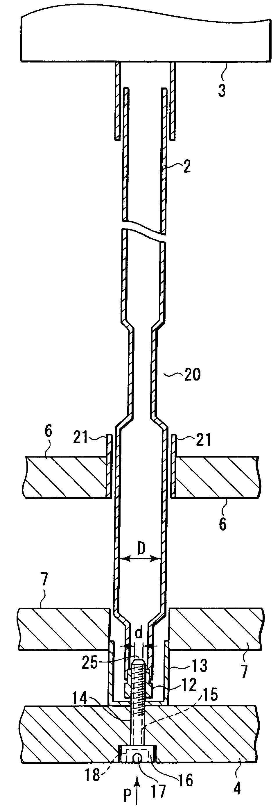
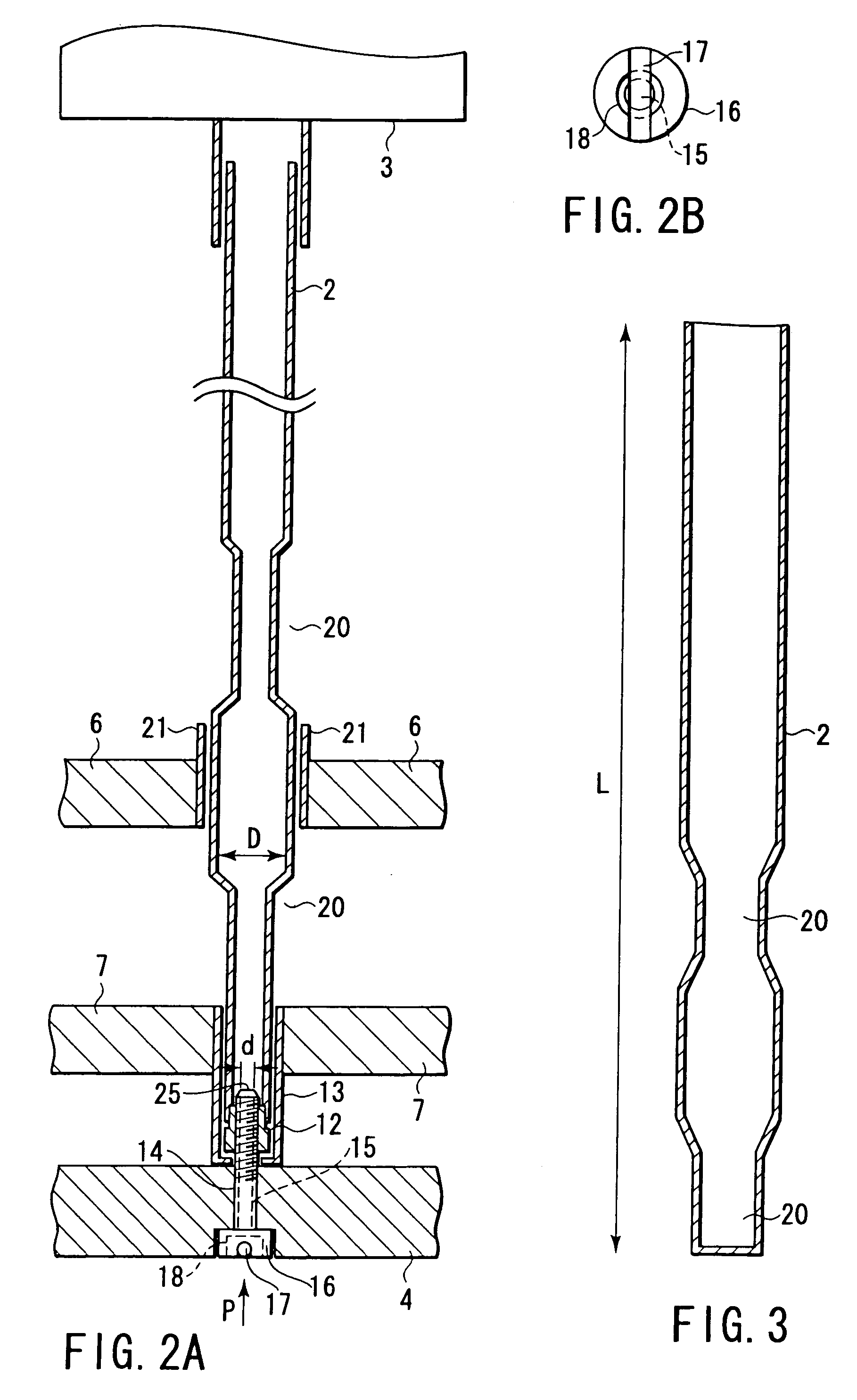
[0057]In a fuel assembly according the first embodiment of the present invention, the structure of a connecting portion for connecting its guide thimbles 2 and bottom nozzle 4 is as shown in FIGS. 2B and 4 or 5, and a so-called improved guide thimble is employed. An inner diameter D of the lower large-diameter portion of the guide thimble 2 and a diameter d of a drain hole 15 satisfy the following equation (1):

0.04 D

[0058]The function of the fuel assembly according to this embodiment with the above arrangement will be described.

[0059]FIG. 6 is a graph showing results obtained by measuring a terminal velocity V of a control rod inserted in the guide thimble 2 by free fall in a fuel assembly 1 formed as shown in FIGS. 4 and 5, by using (d / D), which is the ratio of the diameter d of the drain hole 15 of a thimble screw 14 to the inner diameter D of the lower large-diamete...

second embodiment

[0070]The second embodiment of the present invention will be described with reference to FIG. 8 and FIGS. 9A to 9C.

[0071]FIG. 8 is a view showing a state wherein a rotation preventive pin 17 for a thimble screw 14 in a fuel assembly according to the present invention is built into the thimble screw 14.

[0072]FIGS. 9A, 9B, and 9C are views each showing a rotation preventive pin for a thimble screw in the fuel assembly according to this embodiment.

[0073]As shown in FIG. 8, a shaft 23 of the thimble screw 14 has a guide hole 24 as a hole extending from a spot facing hole 18 of a seat 16 to a drain hole 15 on the distal end side in the longitudinal direction of the thimble screw 14. With the rotation preventive pin 17 being mounted in the spot facing hole 18, during operation of the nuclear reactor, a coolant enters from the spot facing hole 18 of the seat 16 as shown in the direction indicated by an arrow A and is drained from a drain hole distal end 25. If the control rod is dropped in...

third embodiment

[0079]The third embodiment of the present invention will be described with reference to FIGS. 10 and 11.

[0080]FIGS. 10 and 11 are views each showing a thimble screw in a fuel assembly according to this embodiment.

[0081]In a thimble screw 14 for the fuel assembly according to this embodiment, a guide hole 24 is formed in the thimble screw 14 on a distal end side 31, and a drain hole 15 is arranged in the thimble screw 14 on a seat 16 side.

[0082]Referring to FIG. 10, a shaft 23 of the thimble screw 14 has the drain hole 15 extending between the guide hole 24 and a spot facing hole 18 of the seat 16. The opening area of the drain hole 15 is set smaller than the opening area of the guide hole 24 or the opening area of the spot facing hole 18. With a rotation preventive pin 17 being mounted in the spot facing hole 18, during operation of the nuclear reactor, a coolant enters from the spot facing hole 18 of the seat 16 in the direction of an arrow A in FIG. 10 and is drained from a guide ...


PUM


Abstract

A fuel assembly includes a bottom nozzle set on a lower core plate of a nuclear reactor, a top nozzle with a hold down spring to urge the bottom nozzle against the lower core plate, guide thimbles which guide control rods, having passed through the top nozzle, toward the lower core plate, a dashpot formed on each of the guide thimbles to reduce the fall velocity of a corresponding one of the control rods, a thimble screw which connects each of the guide thimbles to the bottom nozzle, and a drain hole formed to extend through each of the thimble screw. The dashpot has a large-diameter portion with substantially the same diameter as that of each of the guide thimbles. The diameter d of the drain hole falls within a range of 0.04 D<d<0.08 D where D is an inner diameter of the large-diameter portion.

Description

CROSS-REFERENCE TO RELATED APPLICATIONS[0001]This application is based upon and claims the benefit of priority from the prior Japanese Patent Applications No. 2001-107148, filed Apr. 5, 2001, No. 2001-129035, filed Apr. 26, 2001; and No. 2002-013333, filed Jan. 22, 2002, the entire contents of all of which are incorporated herein by reference.BACKGROUND OF THE INVENTION[0002]1. Field of the Invention[0003]The present invention relates to a fuel assembly used in a nuclear reactor, and a thimble screw of the fuel assembly.[0004]2. Description of the Related Art[0005]An example of a nuclear reactor currently widely used for power generation includes a pressurized water reactor (to be referred to as “PWR” hereinafter). A fuel assembly used by the PWR is generally a canless fuel assembly with no wrapper tube. The structure of the canless fuel assembly will be briefly described. Top and bottom nozzles each having a plurality of coolant flow holes are connected to each other with a plurali...

Claims


Application Information

Patent Timeline
Patent Type & Authority Patents(United States)
IPC IPC(8): G21C3/32G21C7/20
CPCG21C3/32G21C7/20G21Y2002/304G21Y2004/30Y02E30/39Y02E30/30
Inventor YAMADA, MASAHIKONUNOKAWA, KOICHI
Owner MITSUBISHI HEAVY IND LTD
Why Eureka
Try Eureka