Jet mill

a jet mill and milling machine technology, applied in the field of jet mills, can solve the problems of difficult to grind the material to a specified particle size or control the particle size distribution to a narrow enough range, poor classification precision, swirling, etc., and achieves the effect of easy separation and reassembling, simple configuration, and easy cleaning

Active Publication Date: 2007-08-21
NISSHIN ENG
View PDF15 Cites 16 Cited by
  • Summary
  • Abstract
  • Description
  • Claims
  • Application Information

AI Technical Summary

Benefits of technology

[0008]The present invention has been accomplished under these circumstances and has as an object providing a jet mill that solves the aforementioned problems of the prior art by ensuring that fine particles obtained by the grinding process has the desired particle size with a narrower size distribution of a higher classification precision and which still retains the three advantageous features of the jet mill, that is, the interior of the grinding chamber is simple in configuration, the top and bottom surfaces of the grinding chamber are easy to be separated and reassembled, and cleaning can easily be done both before and after operation.
[0021]As described below in detail, the jet mill of the present invention has a first annular constricted passageway (classification ring channels) and more preferably further has a second annular constricted passageway (exit ring channel) and, as a result, it is characterized by ensuring that fine particles has the desired particle size with a narrower size distribution and which still retains the three advantageous features of the jet mill, that is, the interior of the grinding chamber is simple in configuration, the top and bottom surfaces of the grinding chamber are easy to separate and reassemble, and cleaning can easily be done both before and after operation.

Problems solved by technology

On the other hand, the jet mill relies solely upon the air flow to grind the material in the grinding chamber, so it is difficult to grind the material to a specified particle size or control the particle size distribution to a narrow enough range.
However, although enabling control of the ground particle size distribution over a wide range, the swirling fluid-energy mill disclosed in JP 52-44450 A suffers from a problem of a poor classification precision, since the mill injects compressed air to grind a material and at the same time forms swirling flow to perform classification, thereby also ejecting yet large particles.
And, the horizontal swirling flow jet mill disclosed in JP 63-319067 A, while resolving the problem of a poor classification precision of the mill of JP 52-44450 A, has problems such as that a turbulence is generated in swirl and that fine particles adhere to the rotor wall, due to a difference in speed between the swirling flow formed by the compressed air and that formed by the classification rotor.
Furthermore, the jet mills disclosed in JP 57-84756 A, JP 4-210252 A and JP 6-254427 A, while improving the grinding efficiency, have problems such as that the impact member obstructs the air flow, generating a significant turbulence in the swirling flow to thereby lower the classification precision or to allow the ground material to heavily adhere to the impact member, resulting in difficulty with a stable (continuous) operation.
Moreover, these prior arts all require that complexly shaped mechanical parts be additionally provided inside the grinding chamber, as exemplified by the special mechanism for adjusting the angle at which the air flow is injected, the special mechanism for classification, and the special impact members provided inside the grinding chamber.
Therefore, the aforementioned prior arts have not been completely satisfactory.

Method used


Image

  • Jet mill
  • Jet mill
  • Jet mill

Examples


example 1

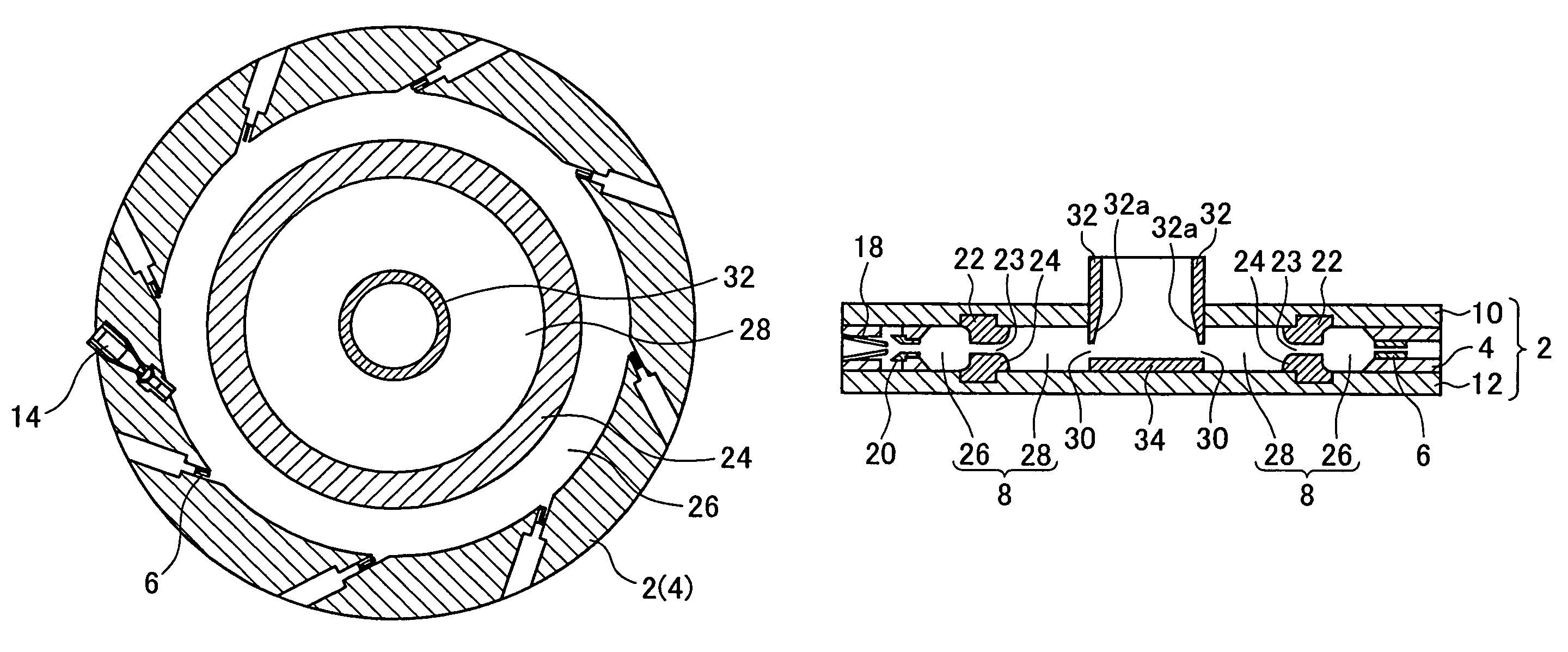
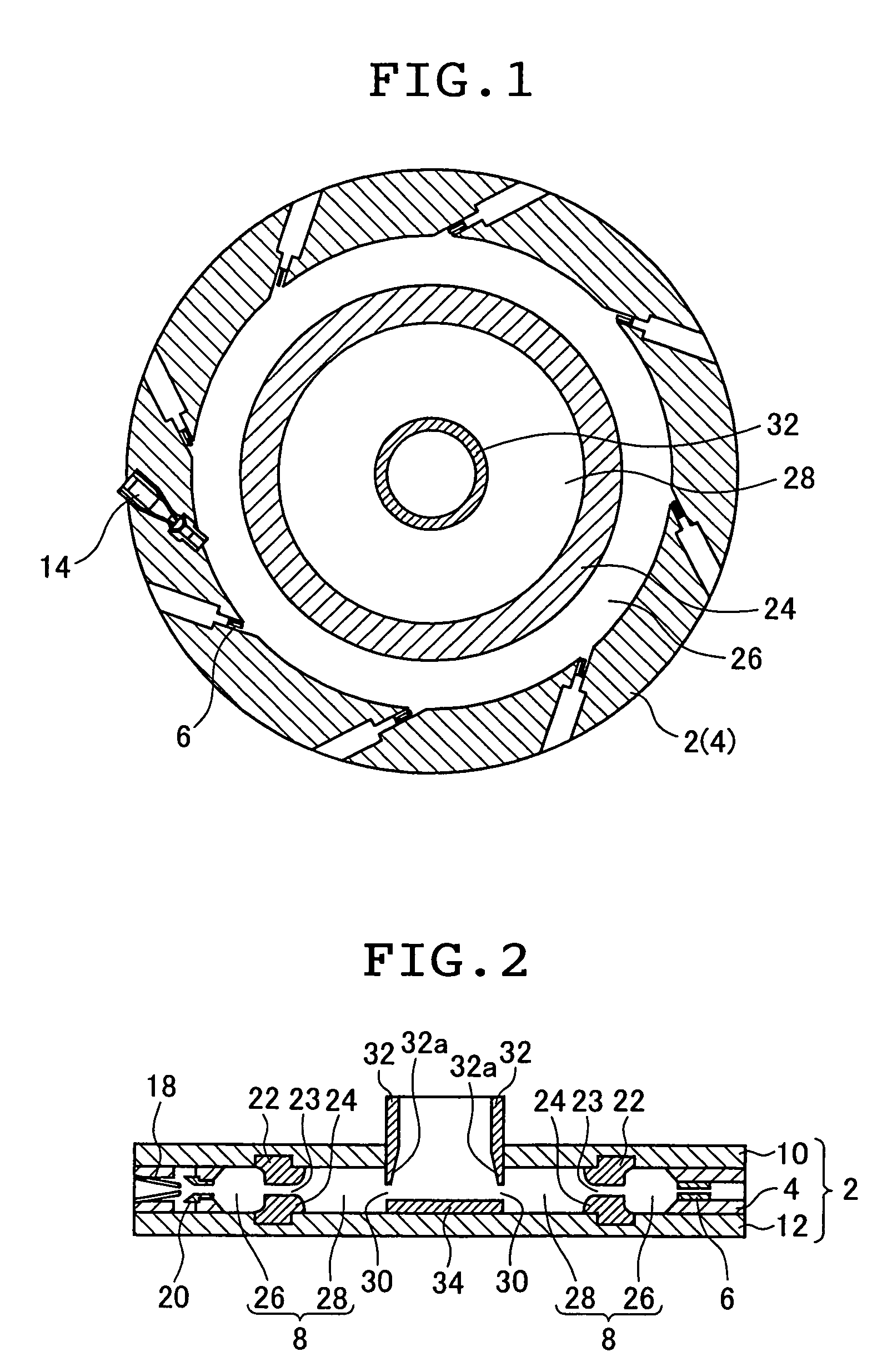
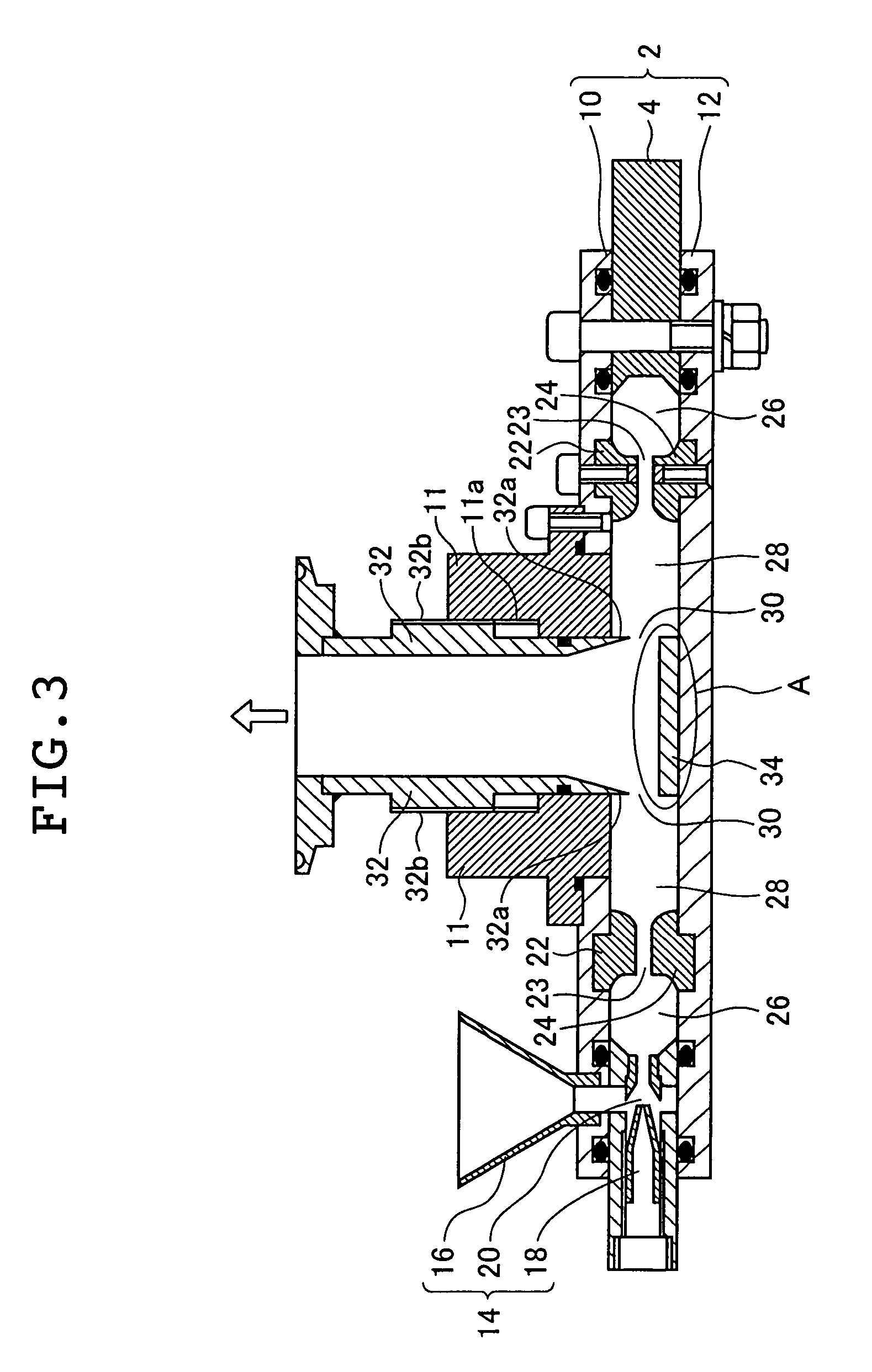
[0055]Polyester-based nonmagnetic color toner particles with an average size of 500 μm was ground with the jet mill shown in FIGS. 1 to 3, and the effectiveness of a classification ring channel 23 formed by classification rings 22 and 24 as annular barriers in the process of grinding was evaluated. Compressed air was supplied through the air nozzles 6 at a pressure of 0.6 MPa and the feed was supplied at a rate of 800 g / hr. The fine particles obtained by the grinding process had an average particle size of 6.4 μm, with the volume fraction of particles finer than 3 μm being 3.9% and that of particles coarser than 10 μm being 1.8% in the presence of the classification ring channel 23. At this time, the mill body 2 had a diameter of 285 mm; the gap spacing between the top plate 10 and the bottom plate 12, that is, the height of the grinding chamber 8, was 20 mm; and the distance between the classification rings 22 and 24 (the opening width of the classification ring channel 23) was 4 m...

example 2

[0058]As in Example 1, polyester-base nonmagnetic color toner particles having an average size of 500 μm were fed as the material to be ground and the grinding process was performed with the distance between the classification rings 22 and 24 (the opening width of the classification ring channel 23) being varied. The average size of the fine particles obtained by the grinding process was measured. Compressed air was supplied through the air nozzles 6 at a pressure of 0.5 MPa and the feed was supplied at a rate of 500 g / hr. The fine particles obtained by the grinding process had average particle sizes of 7.3 μm, 6.3 μm and 5.8 μm with distance between the classification rings 22 and 24 adjusted to 4 mm, 6 mm and 18 mm, respectively.

[0059]Obviously, the average size of the fine particles obtained by the grinding process decreased as the distance between the classification rings 22 and 24 (the opening width of the classification ring channel 23) was increased and vice versa. Thus, it w...

example 3

[0061]As in Example 1, polyester-based nonmagnetic color toner particles having an average size of 500 μm were ground but this time for the purpose of evaluating the effectiveness of the exit ring channel 30 in the process of grinding with jet mills. In this experiment, compressed air was supplied through the air nozzles 6 at a pressure of 0.5 MPa and the feed was supplied at a rate of 500 g / hr. When the jet mill had the exit ring channel 30 as in the invention, the fine particles obtained by the grinding process had an average particle size of 7.3 μm, with the volume fraction of particles coarser than 10 μm being 5.2% and that of particles coarser than 16 μm being 0.0%.

[0062]On the other hand, without the exit ring channel 30, the fine particles obtained by the grinding process had an average particle size of 10.7 μm, with the volume fraction of particles coarser than 10 μm being 56.6% and that of particles coarser than 16 μm being 5.0%.

[0063]Thus, by providing the exit ring channe...


PUM


Abstract

A jet mill has a disk-shaped hollow part in the interior of the mill body. The hollow part is divided into an annular grinding zone for grinding a material by high-speed swirling air flows supplied through plural air nozzles and an annular classifying zone provided inside the grinding zone and communicated to an exit space for classifying the ground material by the swirling air flows in the grinding zone. An annular first constricted passageway is arranged between the grinding zone and the classifying zone to thereby divide and communicate them, and preferably an annular second constricted passageway between the classifying zone and the inside exit thereof. Accordingly, a jet mill realizing a high classification precision for a desired particle size of ground material with a narrow size distribution and having a simple inner configuration to allow easy cleaning before and after operation can be provided.

Description

BACKGROUND OF THE INVENTION[0001]This invention relates to a jet mill in which a high-speed air flow is supplied into a grinding chamber of a hollow part in the interior of the mill body through air nozzles inclined on the outer wall so that the coarser powder (the material to be ground) is continuously ground to fine particles (fine powder) of micron-order size in the grinding chamber while at the same time classification is effected by the swirling air flow.[0002]In jet mills, a high-speed air flow is supplied into the grinding chamber through the air nozzles inclined on the outer wall so that the coarser material to be ground is reduced in size as it swirls and classification is also effected by the swirling air flow. Jet mills are known as grinding devices suitable for yielding superfine products (particles). They are characterized in that the interior of the grinding chamber is simple in configuration, the top and bottom surfaces of the grinding chamber are easy to separate and...

Claims


Application Information

Patent Timeline
Patent Type & Authority Patents(United States)
IPC IPC(8): B02C11/08B02C19/06B02C23/10
CPCB02C19/063B02C23/10B02C19/061B02C19/005B02C23/08
Inventor TAKETOMI, KENJIKOZAWA, KAZUMIAKIYAMA, SATOSHI
Owner NISSHIN ENG
Why Eureka
Try Eureka