
Method of controlling drive of function liquid droplet ejection head; function liquid droplet ejection apparatus; electro-optic device; method of manufacturing LCD device, organic EL device, electron emission device, PDP device, electrophoretic display device, color filter, organic EL; method of forming spacer, metallic wiring, lens, resist, and light diffusion body

a technology of liquid droplet ejection and drive signal, which is applied in the direction of electrode system manufacturing, electric discharge tube/lamp manufacturing, instruments, etc., can solve the problems of drive signal lowering printing throughput and complicated control of ink jet head drive, and achieve the effect of quick and easy manufactur

Active Publication Date: 2007-08-21
KATEEVA
View PDF21 Cites 44 Cited by
  • Summary
  • Abstract
  • Description
  • Claims
  • Application Information

AI Technical Summary

Benefits of technology

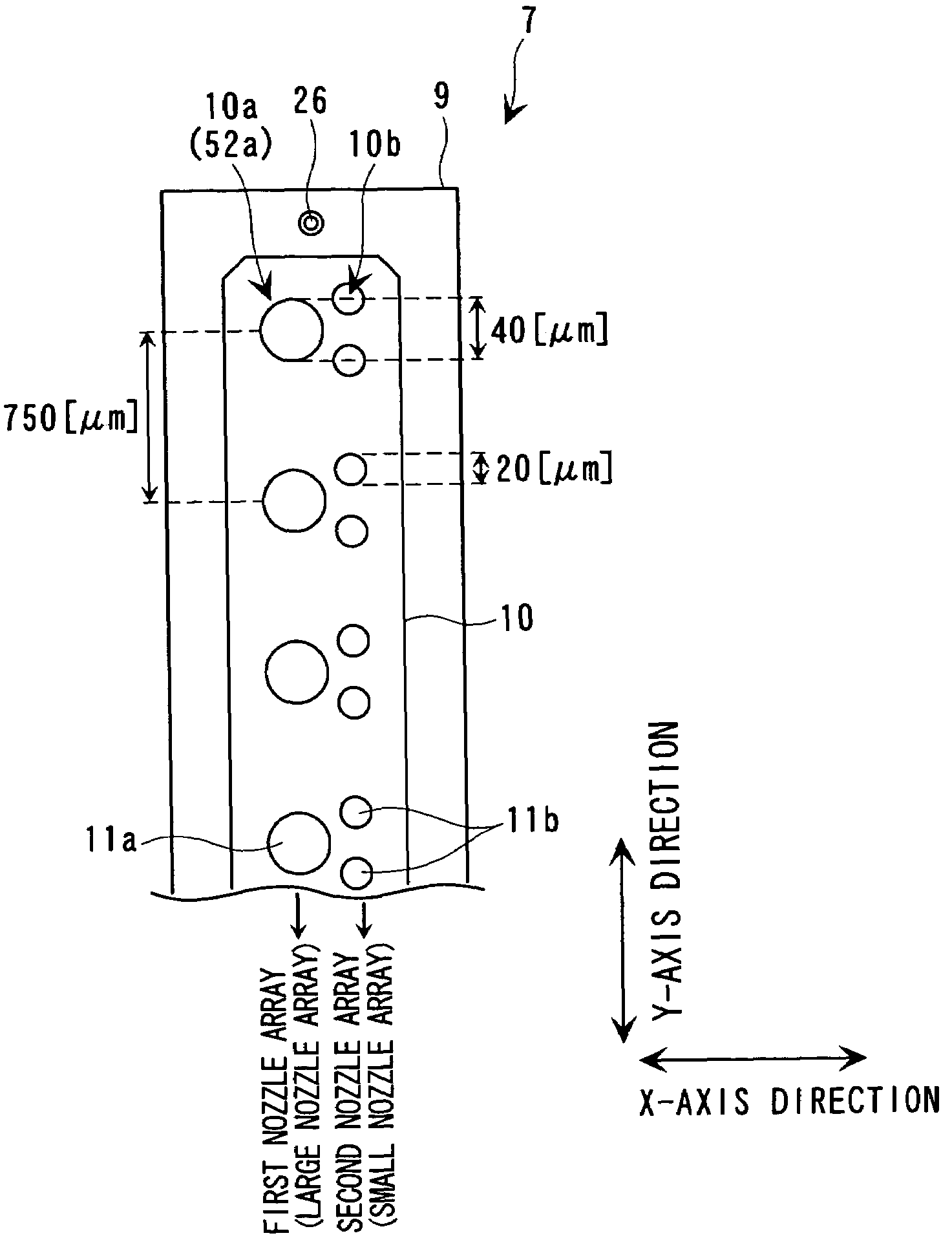
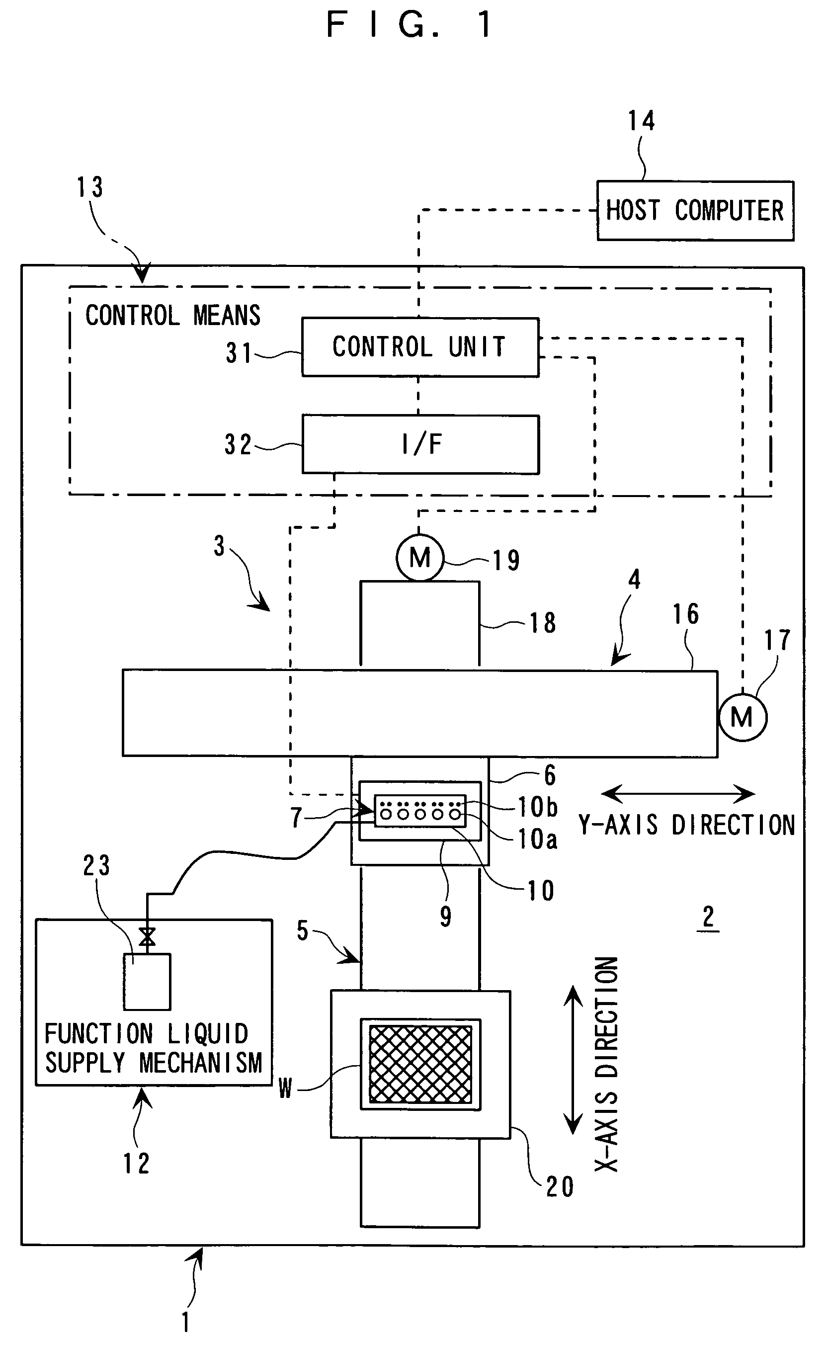
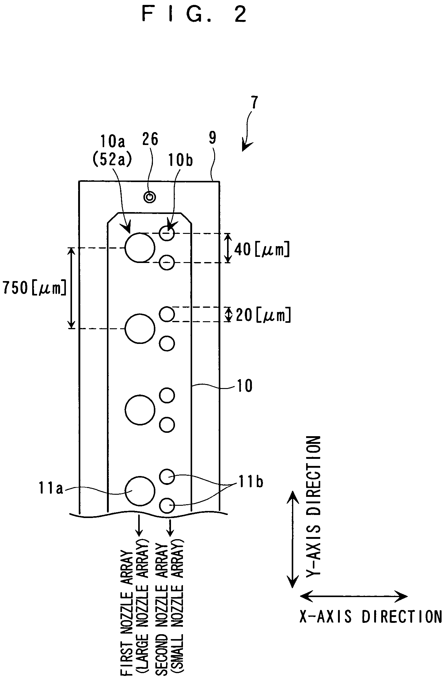
The invention provides a method for controlling a function liquid droplet ejection head with multiple nozzle arrays that have different function liquid droplet ejection amounts per unit nozzle. This method allows for efficient ejection of function liquid within one pixel and uniform film thickness. The control is achieved by using a single drive signal with multiple ejection pulses corresponding to the nozzle arrays. The method also allows for flushing, which is function recovery processing by waste discharging of liquid droplets from all nozzles, by using an identical ejection pulse. The invention also provides a method for preventing the thickening of function liquid near the nozzle orifice part by using micro oscillation pulses. The invention further provides a method for improving printing throughput by shortening the print cycle and reducing the influence on printing throughput caused by the thickening of function liquid.

Problems solved by technology

Thus, there is a problem in that control of drive of the ink jet head becomes complicated.
However, with this arrangement, there is assumed to be a problem in that time required for switching the drive signals lowers printing throughput.

Method used


Image

  • Method of controlling drive of function liquid droplet ejection head; function liquid droplet ejection apparatus; electro-optic device; method of manufacturing LCD device, organic EL device, electron emission device, PDP device, electrophoretic display device, color filter, organic EL; method of forming spacer, metallic wiring, lens, resist, and light diffusion body
  • Method of controlling drive of function liquid droplet ejection head; function liquid droplet ejection apparatus; electro-optic device; method of manufacturing LCD device, organic EL device, electron emission device, PDP device, electrophoretic display device, color filter, organic EL; method of forming spacer, metallic wiring, lens, resist, and light diffusion body
  • Method of controlling drive of function liquid droplet ejection head; function liquid droplet ejection apparatus; electro-optic device; method of manufacturing LCD device, organic EL device, electron emission device, PDP device, electrophoretic display device, color filter, organic EL; method of forming spacer, metallic wiring, lens, resist, and light diffusion body

Examples


Embodiment Construction

[0068]Hereinafter, with reference to the accompanying drawings, descriptions will be made of a method of controlling drive of a function liquid droplet ejection head, a function liquid droplet ejection apparatus, an electro-optic device, a method of manufacturing a liquid crystal display device, a method of manufacturing an organic EL device, a method of manufacturing an electron emission device, a method of manufacturing a PDP device, a method of manufacturing an electrophoretic display device, a method of manufacturing a color filter, a method of manufacturing an organic EL, a method of forming a spacer, a method of forming a metallic wiring, a method of forming a lens, a method of forming a resist, and a method of forming a light diffusion body, according to this invention.

[0069]An ink jet head (function liquid droplet ejection head) of an ink jet printer can accurately eject dot-shaped minute ink droplets (function liquid droplets). Thus, the ink jet head is expected to be appli...


PUM


Abstract

In a method of controlling drive of a function liquid droplet ejection head in which a plurality of nozzle arrays are arranged, the nozzle arrays have function liquid droplet ejection amounts which are different from each other per unit nozzle. The drive of the plurality of nozzle arrays is controlled by using a single drive signal having a plurality of ejection pulses corresponding to the plurality of nozzle arrays in one print cycle. Thus, even if a plurality of nozzle arrays having function liquid droplet ejection amounts which are different from each other per unit nozzle are disposed in one function liquid droplet ejection head, easy drive control is possible without lowering printing throughput.

Description

RELATED APPLICATION[0001]This application claims priority to Japanese Patent Application No. 2003-073689 filed Mar. 18, 2003 which is hereby expressly incorporated by reference herein in its entirety.BACKGROUND OF THE INVENTION[0002]1. Field of the Invention[0003]This invention relates to: a method of controlling drive of a function liquid droplet ejection head having disposed therein a plurality of nozzle arrays with a different function liquid droplet ejection amount per unit nozzle; a function liquid droplet ejection apparatus; an electro-optic device; a method of manufacturing a liquid crystal display device; a method of manufacturing an organic electroluminescence (EL) device; a method of manufacturing an electron emission device; a method of manufacturing a plasma display panel (PDP) device; a method of manufacturing an electrophoretic display device; a method of manufacturing a color filter; a method of manufacturing an organic EL; a method of forming a spacer; a method of fo...

Claims


Application Information

Patent Timeline
Patent Type & Authority Patents(United States)
IPC IPC(8): B41J29/38B41J2/205B41J2/01B05B12/00B05C5/00B05C11/10B05D1/26B41J2/045B41J2/055B41J2/15G02B5/20G02F1/1335G02F1/1339G02F1/1343H01J9/227H01J11/22H01J11/34H01J11/42H01L51/50H05B33/10
CPCB41J2/04581B41J2/04588B41J2/15Y10T428/24851B41J2002/14475B41J2202/09B41J2/04593B41J2/04596B41J2/2125B41J2/01
Inventor USUDA, HIDENORI
Owner KATEEVA
Learn More