Headlamp

a technology for headlamps and diodes, applied in the field of headlamps, can solve the problems of increasing the temperature of the substrate portion, shortening the life reducing the luminous efficiency of the light-emitting diodes, so as to prevent heat generation

Inactive Publication Date: 2007-08-21
CATEYE
View PDF8 Cites 41 Cited by
  • Summary
  • Abstract
  • Description
  • Claims
  • Application Information

AI Technical Summary

Benefits of technology

[0010]The present invention has been made to solve the above-described problems. An object of the present invention is to provide a headlamp that can prevent heat generated from a light-emitting diode and heat upon bonding the light-emitting diode on a substrate portion from adversely affecting the light-emitting diode and other elements mounted on the substrate portion.
[0012]With this configuration, the heat generated from the light-emitting diode and conducted to the substrate portion is dissipated to the surrounding area, so that the air located in the spacing is warmed. The warmed air in the spacing flows via the vent hole into the battery case where it is cooled, and the cooled air flows via the vent hole back to the spacing where it is warmed again. As this cycle is repeated, the air circulates through the spacing and the inside of the battery case. Accordingly, compared to the case of a conventional headlamp not provided with a vent hole, circulation of the air enables efficient dissipation of the heat of the substrate portion, thereby preventing the heat generated from the light-emitting diode from adversely affecting the light-emitting diode and other elements mounted on the substrate portion.
[0013]Preferably, the vent hole is provided at both an upper portion and a lower portion of a partition separating the spacing from the inside of the battery case, to guide the air warmed and flowing upward in the spacing efficiently to the battery case, and to guide the air cooled and flowing downward in the battery case efficiently to the spacing.
[0015]With this configuration, the heat generated from the light-emitting diode is efficiently conducted to the metal plate, and efficiently dissipated into the air circulating through the spacing and the inside of the battery case.
[0016]Alternatively, the substrate main body of the substrate portion may include a metal plate, and a metal foil formed on the metal plate with a resin interposed therebetween, since the vent hole is provided to efficiently cool the substrate portion.
[0020]With this configuration, since the rivet is hollow, the heat upon soldering the terminal of the light-emitting diode to the rivet is prevented from being conducted to the substrate portion serving as a heat-dissipating plate. Accordingly, it is possible to carry out soldering without applying excessive heat to the part of the substrate portion to which the terminal is connected, thereby suppressing degradation of the elements mounted on the substrate portion.

Problems solved by technology

If the temperature of the bonded portion of the light-emitting diode increases, luminous efficiency of the light-emitting diode decreases, leading to shortening of its life as well.
Further, soldering for bonding the light-emitting diode to the substrate portion increases the temperature of the substrate portion, and the generated heat will affect the elements mounted on the substrate portion, including the light-emitting diode.
With the conventional headlamp employing the light-emitting diode, however, the heat dissipated from the substrate portion will remain around the substrate portion, making it difficult to suppress the temperature increase of the substrate portion.
Further, since the epoxy resin is disposed on the aluminum plate, sufficient conduction of the heat generated from the light-emitting diode or the heat upon soldering the light-emitting diode to the aluminum substrate portion cannot be expected, leading to degradation of the light-emitting diode and others.

Method used


Image

  • Headlamp
  • Headlamp
  • Headlamp

Examples


first embodiment

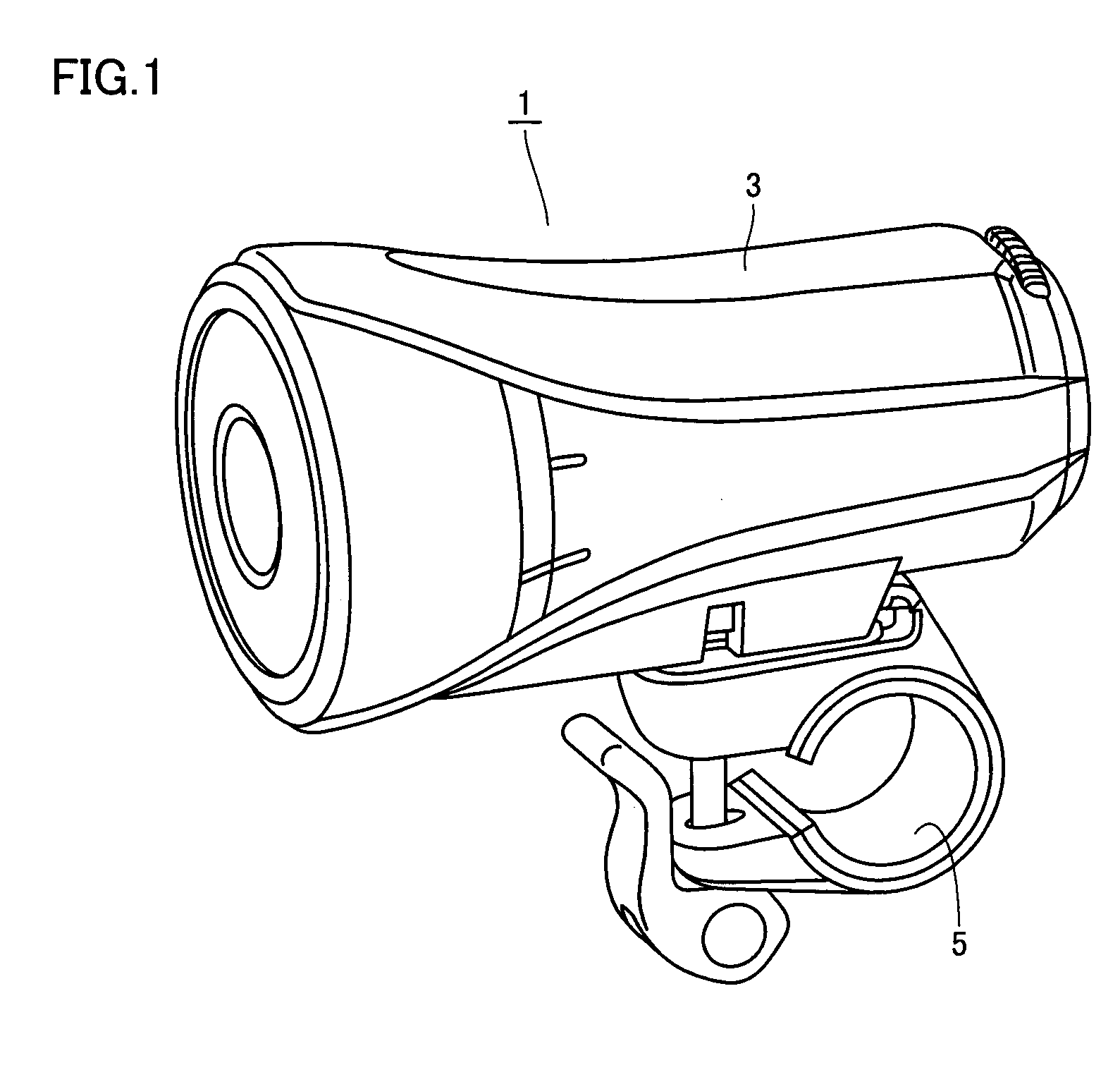
[0032]As an example of the headlamp employing a light-emitting diode according to a first embodiment of the present invention, a headlamp mounted to a bicycle is explained. As shown in FIG. 1, the headlamp 1 has a casing 3 for accommodating a light source, a battery and others to protect them against weather. Casing 3 is provided with an attachment 5 for attaching headlamp 1 to, e.g., a handlebar (not shown) of a bicycle.

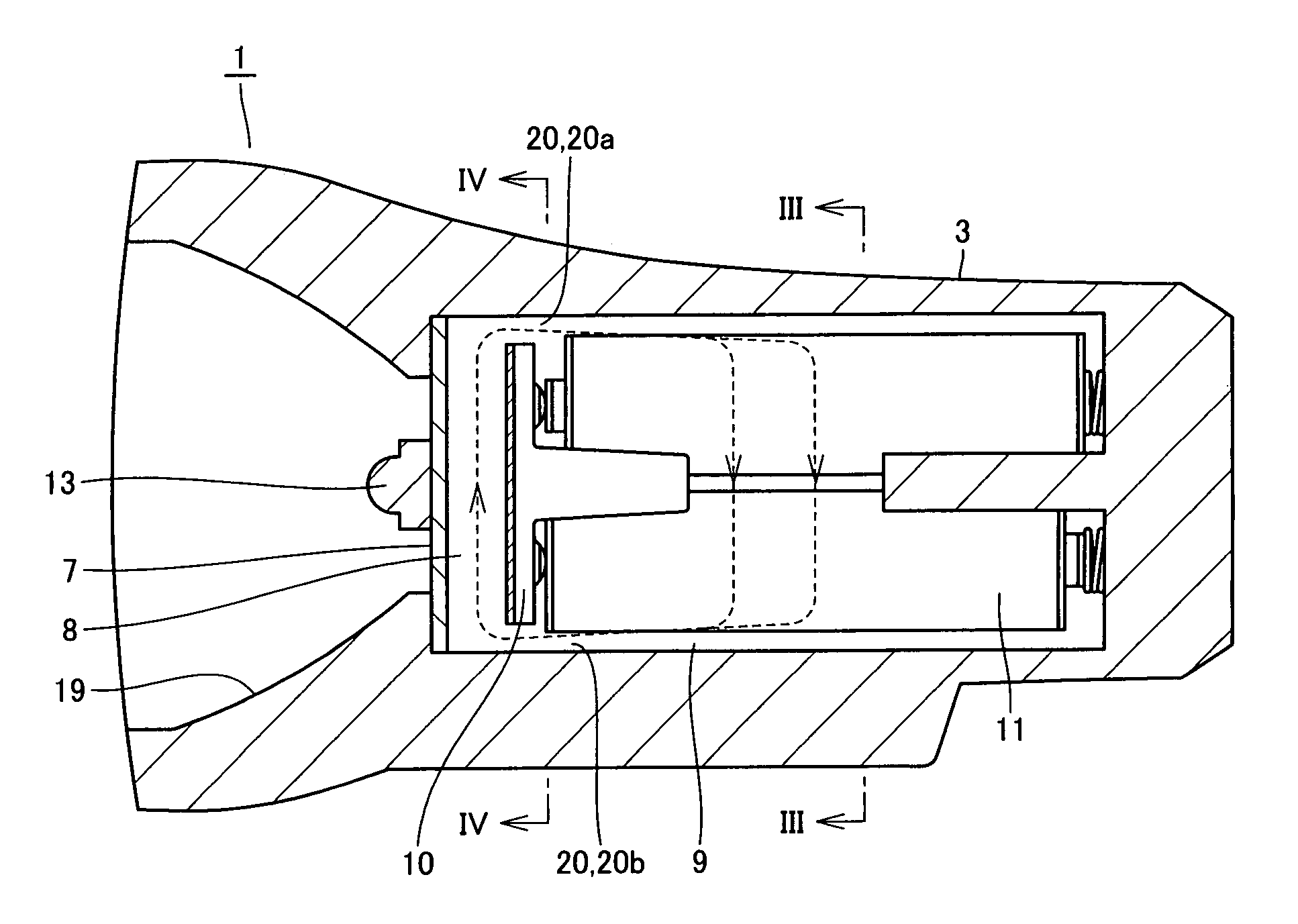
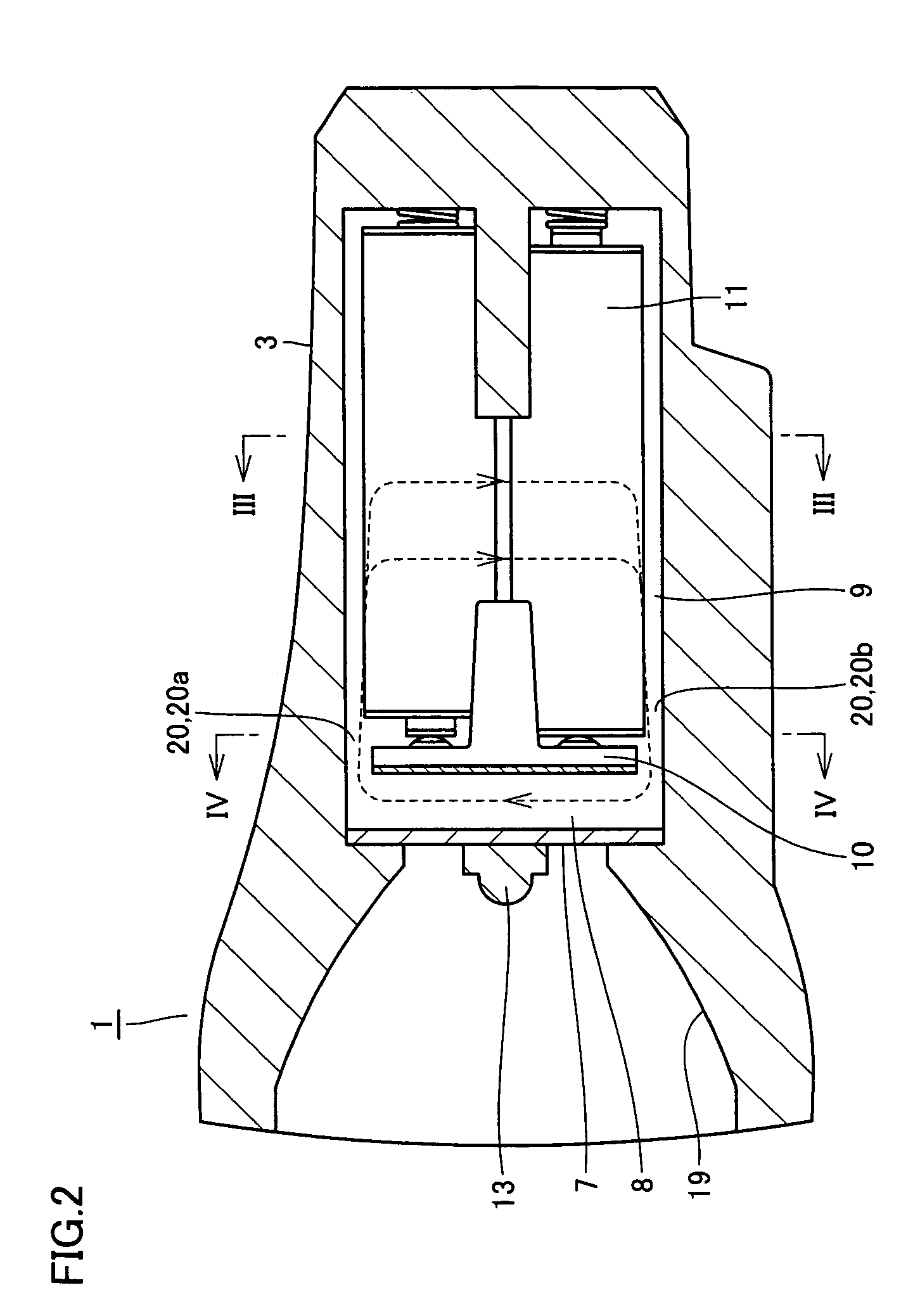
[0033]As shown in FIG. 2, provided within casing 3 of headlamp 1 are a substrate portion 7 to which a light-emitting diode 13 as the light source is mounted, and a battery case 9 for housing a battery 11 for supplying necessary power to light-emitting diode 13. A reflecting mirror 19 is provided on the same side as light-emitting diode 13, for directing the light emitted from light-emitting diode 13 frontward.

[0034]Substrate portion 7, mounted with light-emitting diode 13 and serving as a heat sink, is arranged spaced apart from a partition 10 positioned on the fron...

second embodiment

[0042]A headlamp employing a light-emitting diode according to a second embodiment of the present invention is now described. In the present embodiment, as shown in FIG. 7, a substrate portion 7 to which a light-emitting diode 13 is mounted is formed only of an aluminum plate 7a. Light-emitting diode 13 is mounted to a holder 15 that is provided directly on a surface of aluminum plate 7a.

[0043]Further, as shown in FIG. 8, substrate portion 7 is provided with a through hole 16 penetrating therethrough. A hollow rivet 17 as a prescribed rivet is mounted to through hole 16.

[0044]As shown in FIGS. 8 and 9, rivet 17 has one end connected to a terminal of light-emitting diode 13, and another end connected to a terminal 12 provided on partition 10 of battery case 9 for providing power.

[0045]As described above, in the headlamp of the present embodiment, substrate portion 7 formed only of aluminum plate 7a is employed for substrate portion 7 to which light-emitting diode 13 is mounted. As s...


PUM


Abstract

In a casing of a headlamp, a substrate portion to which a light-emitting diode as a light source is mounted, and a battery case accommodating a battery for providing necessary power to the light-emitting diode are provided. The substrate portion is spaced apart from a partition disposed on the front side of the battery case, with spacing provided therebetween. The partition is provided with a vent hole, having an upper vent hole and a lower vent hole, for establishing communication of the spacing between the substrate portion and the partition with the space within the battery case, for circulation of the air. Thus, a headlamp capable of suppressing adverse effects of the heat generated from the light-emitting diode or the like on the elements mounted on the substrate is provided.

Description

BACKGROUND OF THE INVENTION[0001]1. Field of the Invention[0002]The present invention relates to a headlamp, and more particularly to a headlamp employing a light-emitting diode.[0003]2. Description of the Background Art[0004]Conventionally, a light bulb was used for a headlamp mounted to a bicycle or the like, as in Japanese Utility Model Laying-Open No.02-031003. In recent years, however, with advancement of semiconductor elements and from the standpoint of low power consumption, a light-emitting diode has been adopted. In the headlamp employing the light-emitting diode, the light-emitting diode is mounted on a substrate portion and arranged within a prescribed casing, and is provided with necessary power from a battery housed in a battery case within the casing to turn on a light.[0005]When the intensity of the light emitted from the light-emitting diode is increased to provide brighter light, heat is also generated from the light-emitting diode. If the temperature of the bonded ...

Claims


Application Information

Patent Timeline
Patent Type & Authority Patents(United States)
IPC IPC(8): F21V29/02B62J6/02F21L2/00F21L4/00F21S8/10F21V15/01F21V29/00F21Y101/02H01L33/00H01L33/60
CPCB62J6/02F21V29/004F21V29/83F21Y2101/02F21W2101/023F21Y2115/10F21W2107/13B62J6/029F21V29/70
Inventor KURUMATANI, TOSHIMITSU
Owner CATEYE
Why Eureka
Try Eureka