Wrought stainless steel compositions having engineered microstructures for improved heat resistance

a technology of microstructure and composition, applied in the direction of heat exchange apparatus, lighting and heating apparatus, etc., can solve the problems of lack of both, lack of heat lack of aging resistance of stainless steels, etc., and achieve the effect of improving heat and corrosion resistan

Inactive Publication Date: 2007-08-21
UT BATTELLE LLC
View PDF11 Cites 52 Cited by
  • Summary
  • Abstract
  • Description
  • Claims
  • Application Information

AI Technical Summary

Problems solved by technology

Currently, stainless steels of types 347, 321, 304, 316 are used, but are limited by their lack of both creep-rupture resistance and corrosion resistance at 700° C. and above, especially with alternate and / or opportunity fuels and more corrosive exhaust environments.
Such stainless steels also lack aging resistance and can loose ductility at low temperatures after aging.
While much more expensive Ni-based or Co-based alloys and superalloys do exist that could be used for such applications, they cost 5-10 times more than commercial Fe—Cr—Ni austenitic stainless steels, and they would make such energy technologies cost-prohibitive.
A particular problem for use of stainless steels and alloys in such applications is that the fine grain size (<20-50 μm diameter) required to make thin section articles, completely changes the relative behavior of many alloys and / or the beneficial / detrimental effects of various alloying elements compared to heavier sections (ie. rolled plate or wrought tubing) with much coarser grain size.
Fine grain size dramatically reduces creep resistance and rupture life, and below some critical grain size (1-5 μm diameter, depending on the specific alloy) the alloy is generally superplastic and not creep resistant at all.
Therefore, fine-grained, thin-section manufacturing can dramatically reverse the relative strengths of various alloys and alter the expected microstructure properties thereof.

Method used


Image

  • Wrought stainless steel compositions having engineered microstructures for improved heat resistance
  • Wrought stainless steel compositions having engineered microstructures for improved heat resistance
  • Wrought stainless steel compositions having engineered microstructures for improved heat resistance

Examples


Embodiment Construction

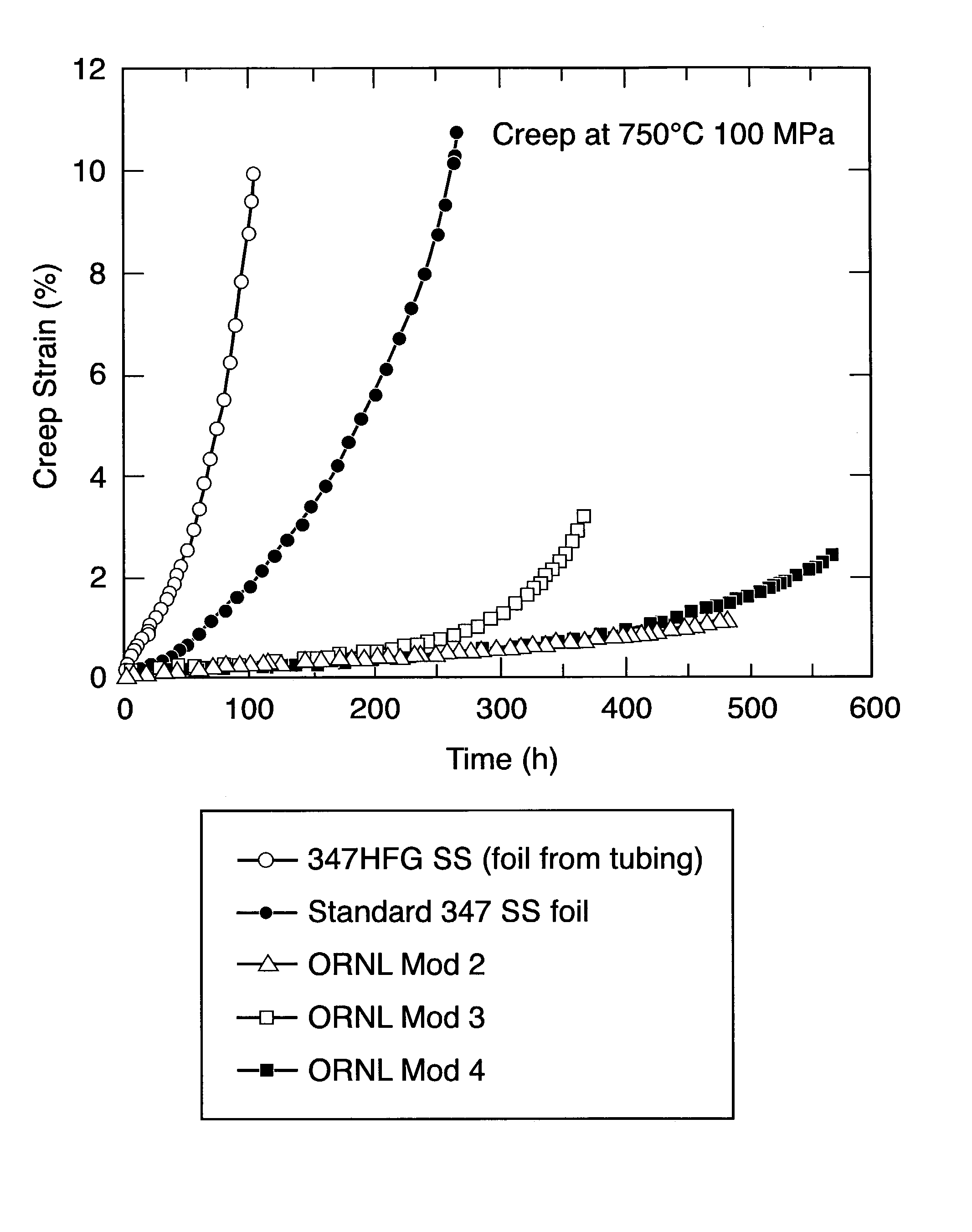
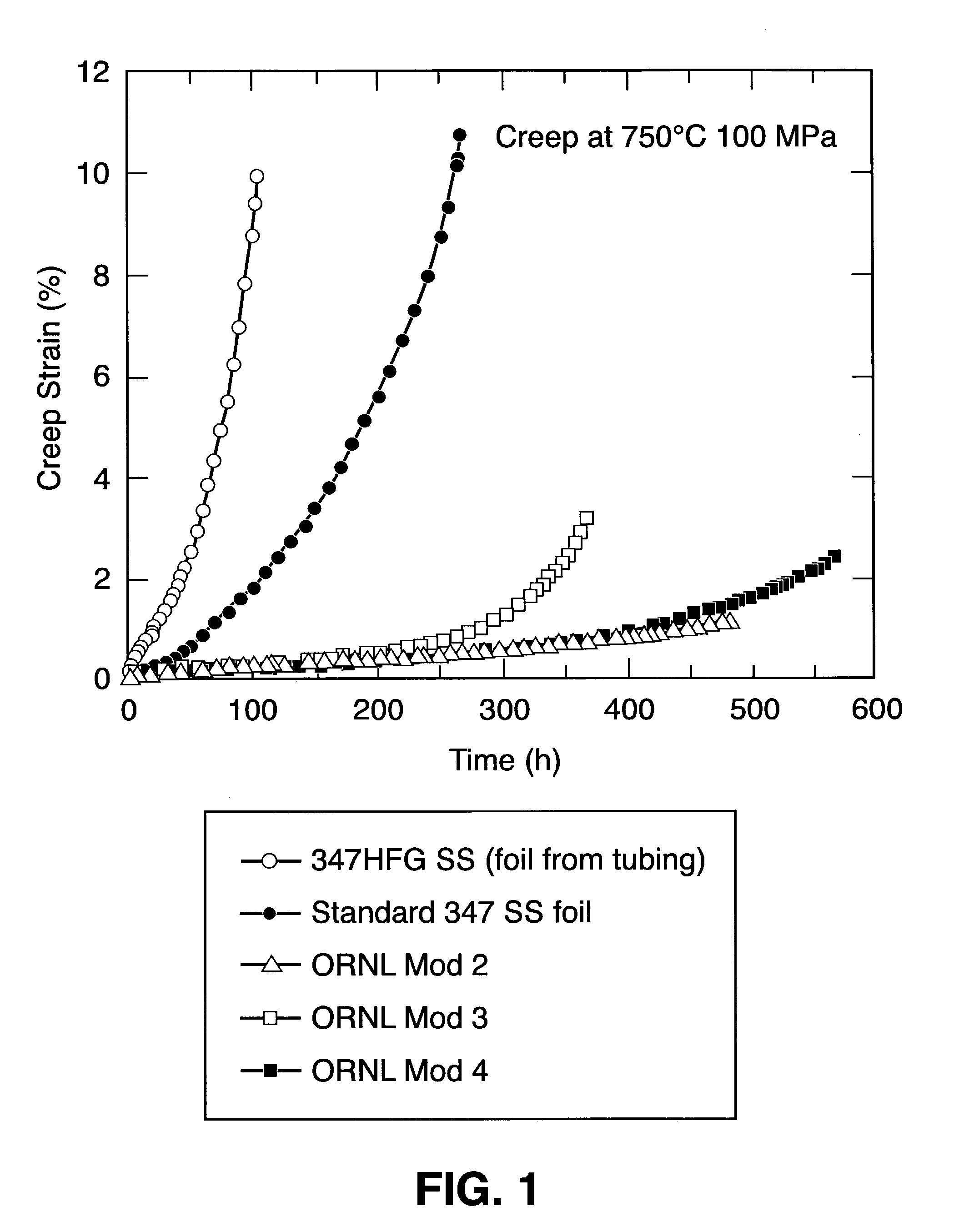
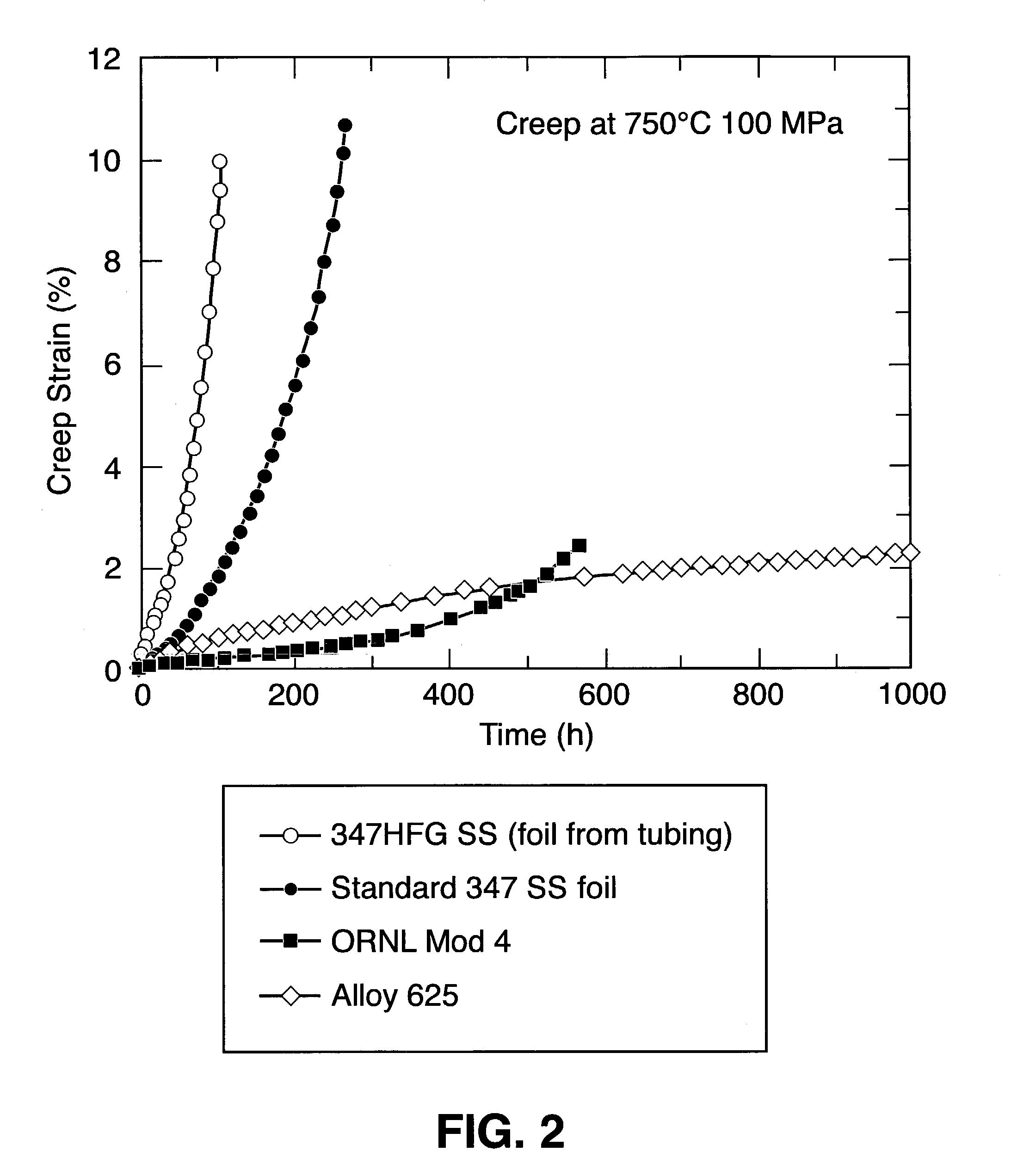
[0022]The present invention arose from the application of unique empirical design rules developed to directly relate changes in alloy composition to changes in the microstructure that develops not during processing or at the time of fabrication of thin-section articles therefrom, but rather subsequently thereto. Engineered microstructures develop during early service, particularly, exposure of the thin-section stainless steel compositions of the present invention to high temperatures, for example, 550° C. to 950° C., and particularly above 650° C.

[0023]The unique design rules may include, but are not limited to:[0024]1. direct reactant effects of elements added to the composition in order to form precipitates;[0025]2. catalytic effects of elements added to the composition to enhance formation of phases formed by other elements;[0026]3. inhibitor effects of elements added to the composition to impede or eliminate formation of phases formed by other elements; and[0027]4. interference ...


PUM

PropertyMeasurementUnit
thicknessaaaaaaaaaa
creep strainaaaaaaaaaa
thicknessaaaaaaaaaa

Abstract

A wrought stainless steel alloy composition includes 12% to 25% Cr, 8% to 25% Ni, 0.05% to 1% Nb, 0.05% to 10% Mn, 0.02% to 0.15% C, 0.02% to 0.5% N, with the balance iron, the composition having the capability of developing an engineered microstructure at a temperature above 550° C. The engineered microstructure includes an austenite matrix having therein a dispersion of intragranular NbC precipitates in a concentration in the range of 1010 to 1017 precipitates per cm3.

Description

[0001]The United States Government has rights in this invention pursuant to contract no. DE-AC05-00OR22725 between the United States Department of Energy and UT-Battelle, LLC.FIELD OF THE INVENTION[0002]The present invention relates to wrought stainless steel compositions, and more particularly to thin-section (e.g., thin plate, sheet, foil, etc.) wrought stainless steels having small grains and engineered microstructures containing austenite having dispersions of at least one of intragranular NbC, intragranular Cu-rich clusters and / or precipitates, and / or Alumina scale.BACKGROUND OF THE INVENTION[0003]New, high-performance high-efficiency compact heat-exchangers are being developed for new distributed power or combined heat and power technologies, such as microturbines, polymer-exchange membrane fuel cells, Stirling engines, gas-cooled nuclear reactors, etc. These power technologies often require thin-section austenitic stainless steels. Currently, stainless steels of types 347, 32...

Claims


Application Information

Patent Timeline
Patent Type & Authority Patents(United States)
IPC IPC(8): C22C38/48C22C38/42C22C38/44C22C38/58
CPCC22C38/001C22C38/02C22C38/06C22C38/42C22C38/48C22C38/52C22C38/54C22C38/58C22C38/44F28F21/083
Inventor MAZIASZ, PHILIP J.SWINDEMAN, ROBERT W.PINT, BRUCE A.SANTELLA, MICHAEL L.MORE, KARREN L.
Owner UT BATTELLE LLC
Why Eureka
Try Eureka