
Image processing system for high performance digital imaging devices

Inactive Publication Date: 2007-08-21
FLASHPOINT TECH
View PDF5 Cites 14 Cited by
  • Summary
  • Abstract
  • Description
  • Claims
  • Application Information

AI Technical Summary

Benefits of technology

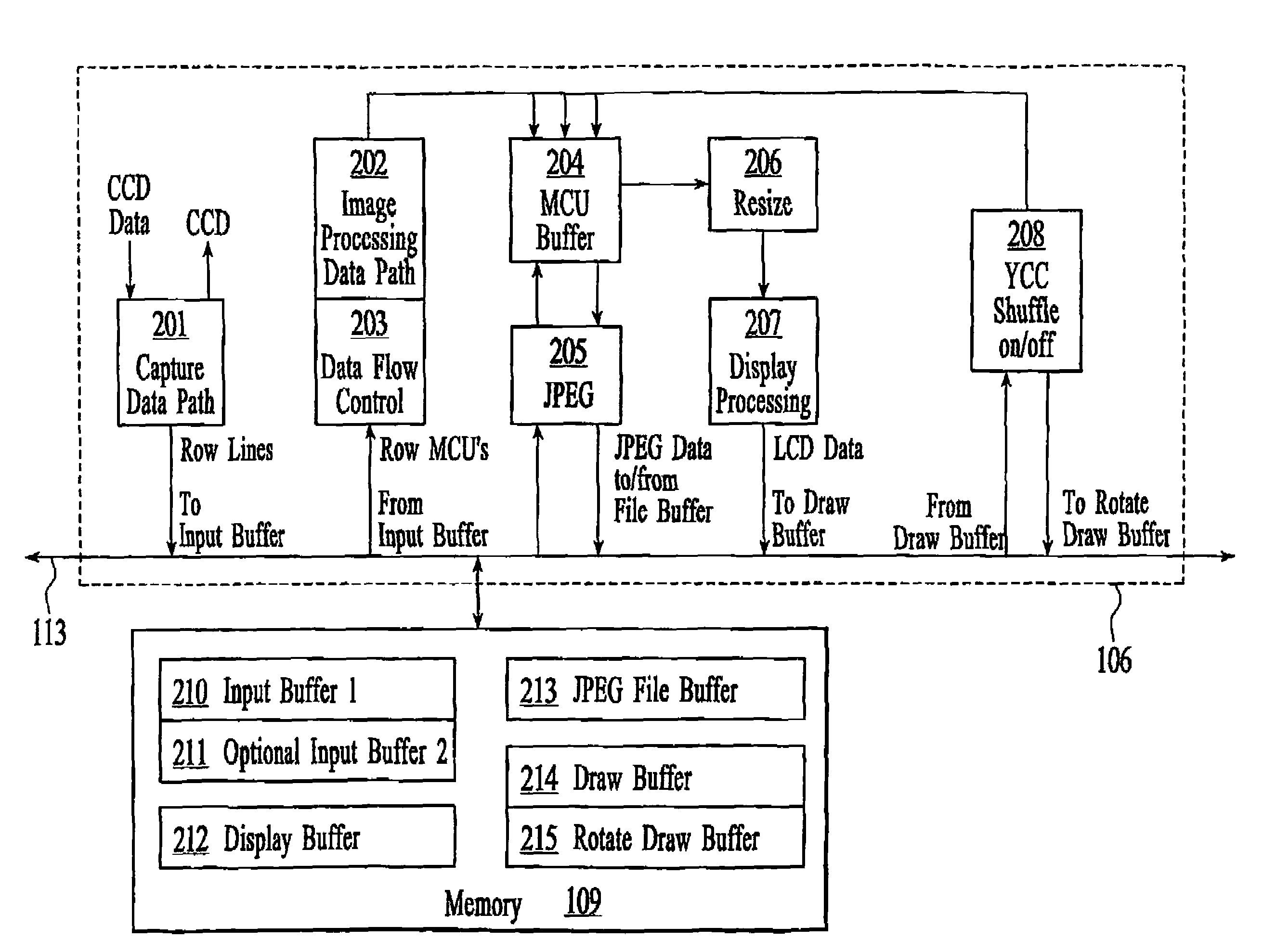
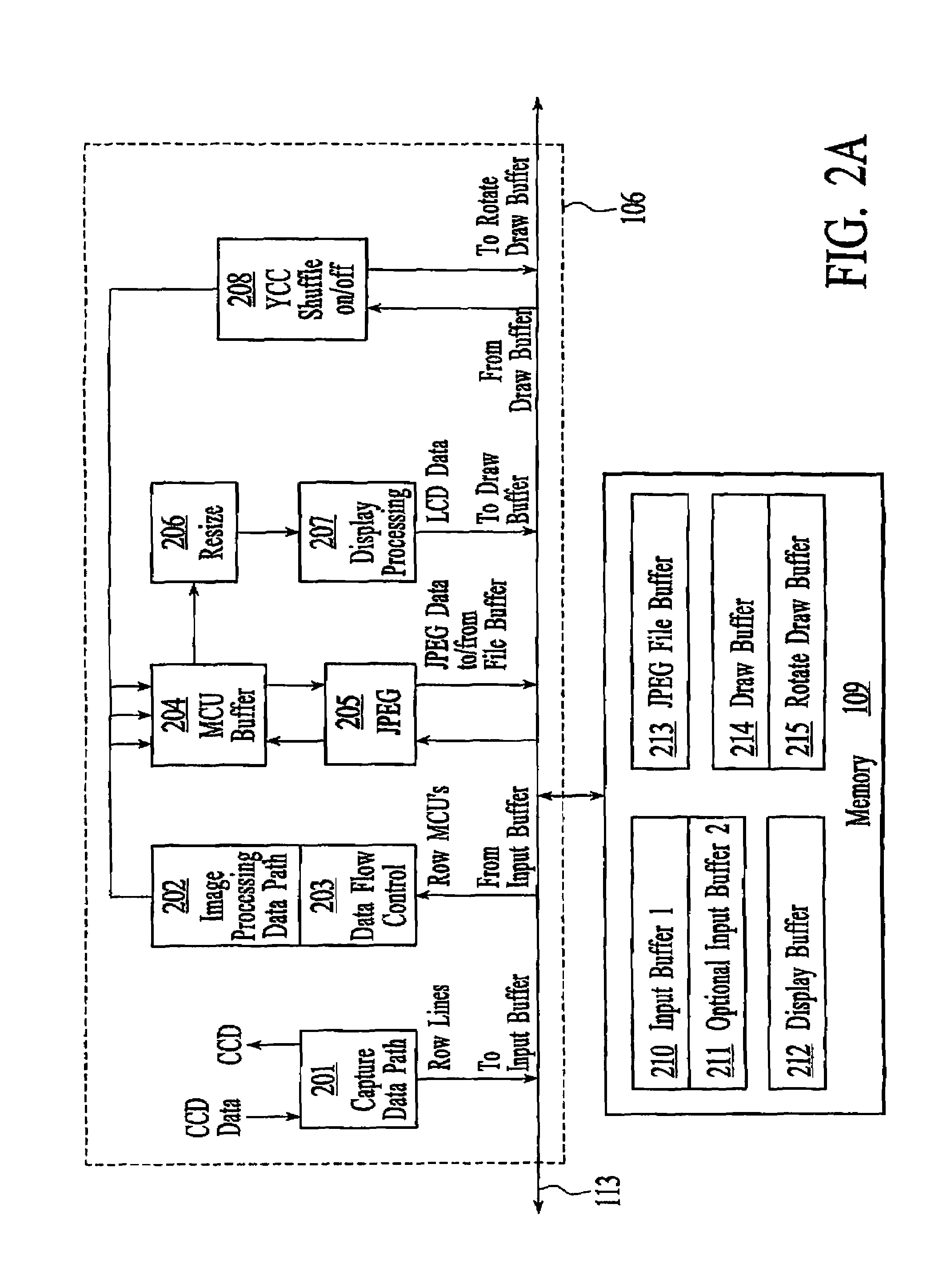
[0011]By utilizing the optimized hardware design and data paths of the present invention, faster image processing can be achieved with a wide range of features, modes of operation, and enhancements. Furthermore, with the novel layout of the hardware design and data paths of the present invention, certain parts and paths can be used in different capacities and in different modes of operation. This reduces the total amount of hardware which is needed, which minimizes the overall cost with minimal or no impact on speed and functionality.

Problems solved by technology

Although this approach makes digital cameras relatively fast, it dramatically increases the overall cost, size, battery consumption, and weight of the digital cameras.
However, this approach suffers from one major drawback; it is relatively slow.
It has been discovered that the software approach is slow because it primarily suffers from two disadvantages.
First, because the advanced features are typically performed by software, it can take a long time to configure and execute the requisite programming steps.
Second, the bus speed becomes a limiting factor as large amounts of data need to be transferred between the processor and memory.
Essentially, the bus becomes overloaded.
The end result is that software-based digital cameras may be too slow to suit the tastes of consumers, depending on the processor / bus combination.

Method used


Image

  • Image processing system for high performance digital imaging devices
  • Image processing system for high performance digital imaging devices
  • Image processing system for high performance digital imaging devices

Examples


Embodiment Construction

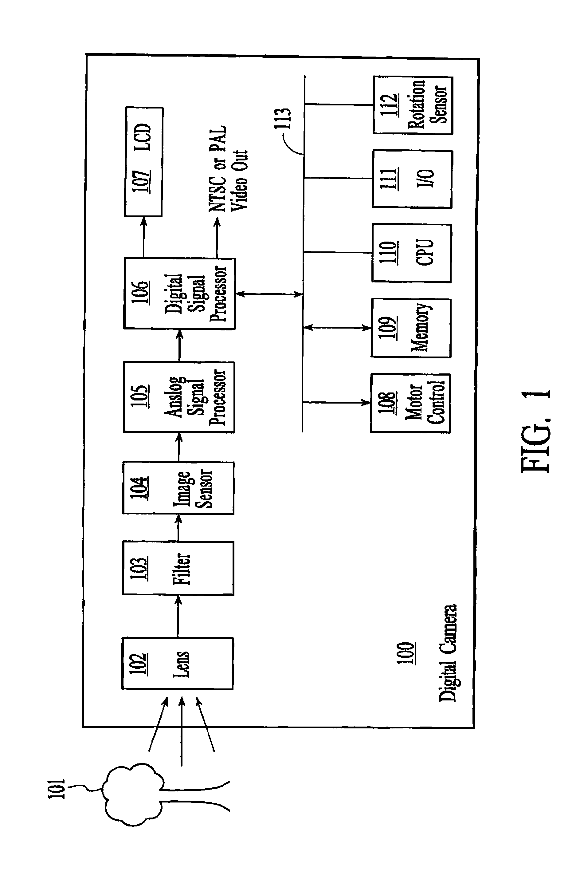
[0026]An imaging system for high performance digital imaging devices is described. The following description is presented to enable one of ordinary skill in the art to make and use the invention and is provided in the context of a patent application and its requirements. Although the present invention is described in the context of a digital camera, various modifications to the preferred embodiment will be readily apparent to those skilled in the art, and the generic principles herein may be applied to other embodiments (e.g., digital scanners, video teleconferencing circuitry, multimedia apparatus, digital VCRs, digital camcorders and recorders, etc.). That is, any image capture device which displays images, icons and / or other items, could incorporate the features described herein below and that device would be within the spirit and scope of the present invention. Thus, the present invention is not intended to be limited to the embodiment shown but is to be accorded the widest scop...


PUM


Abstract

An image processing system for high performance digital imaging in a digital camera. The reflected light from an image is focused through a lens and optically filtered. A CCD array converts this image into an electrical signal. This electrical signal is processed and then converted into an equivalent digital signal. A digital signal processor is then used to process the raw digital signal. The DSP includes a capture data path, a data flow control, an image processing data path, a compression / decompression engine, a resize circuit, a display processing circuit, and a rotation circuit. Data is routed between the DSP and memory via a bus. By selectively activating and reusing certain parts of the hardware architecture and various data paths, at least four modes of operation can be supported: live view, instant review, and play mode. Furthermore, the correct image is automatically displayed in all four modes, regardless of the orientation of the image or the physical orientation of the camera (both at the time the picture was taken and at the time the picture is being rendered for display).

Description

CROSS-REFERENCE TO RELATED APPLICATION[0001]This application is a continuation of and claims the benefit of U.S. patent application Ser. No. 09 / 081,694, filed on May 19, 1998, entitled “IMAGE PROCESSING SYSTEM FOR HIGH PERFORMANCE DIGITAL IMAGING DEVICES,” now issued as U.S. Pat. No. 6,563,535.FIELD OF THE INVENTION[0002]The present invention relates generally to digital cameras, and more particularly to an image processing system for high performance digital imaging.BACKGROUND OF THE INVENTION[0003]Given the rapid advances made in semiconductor technology and digital imaging, it was just a matter of time before digital cameras were developed and introduced. Most digital cameras today are similar in size with and behave similar to conventional photographic cameras. But instead of capturing an image through a lens and recorded onto a photosensitive material as with traditional cameras, digital cameras capture an image using a charge-coupled device (CCD). The composite image is repres...

Claims


Application Information

Patent Timeline
IPC IPC(8): H04N5/228H04N5/76H04N1/21
CPCH04N1/0044H04N1/2112H04N1/2141H04N2201/325
Inventor ANDERSON, ERIC C.
Owner FLASHPOINT TECH
Learn More