Apparatus and method for detecting threats

a technology of threat detection and apparatus, applied in the direction of material analysis using wave/particle radiation, applications, instruments, etc., can solve the problems of difficult movement, inability to obtain the degree of freedom in layout, and heavy apparatus as large as 3 to 7 tons, so as to achieve simplified maintenance

Inactive Publication Date: 2007-08-21
HITACHI LTD +1
View PDF19 Cites 54 Cited by
  • Summary
  • Abstract
  • Description
  • Claims
  • Application Information

AI Technical Summary

Benefits of technology

[0010]By providing two belt conveyors for moving an inspection subject and preventing the belt conveyors from intercepting an X-ray path of an X-ray generator and an X-ray detec...

Problems solved by technology

However, these apparatus are as heavy as 3 tons to 7 tons, and hard to move.
Therefore, the degree of freedom in layout cannot be obtained.
The reasons why thes...

Method used


Image

  • Apparatus and method for detecting threats
  • Apparatus and method for detecting threats
  • Apparatus and method for detecting threats

Examples


Embodiment Construction

[0020]Hereafter, embodiments of the present invention will be described with reference to the drawings.

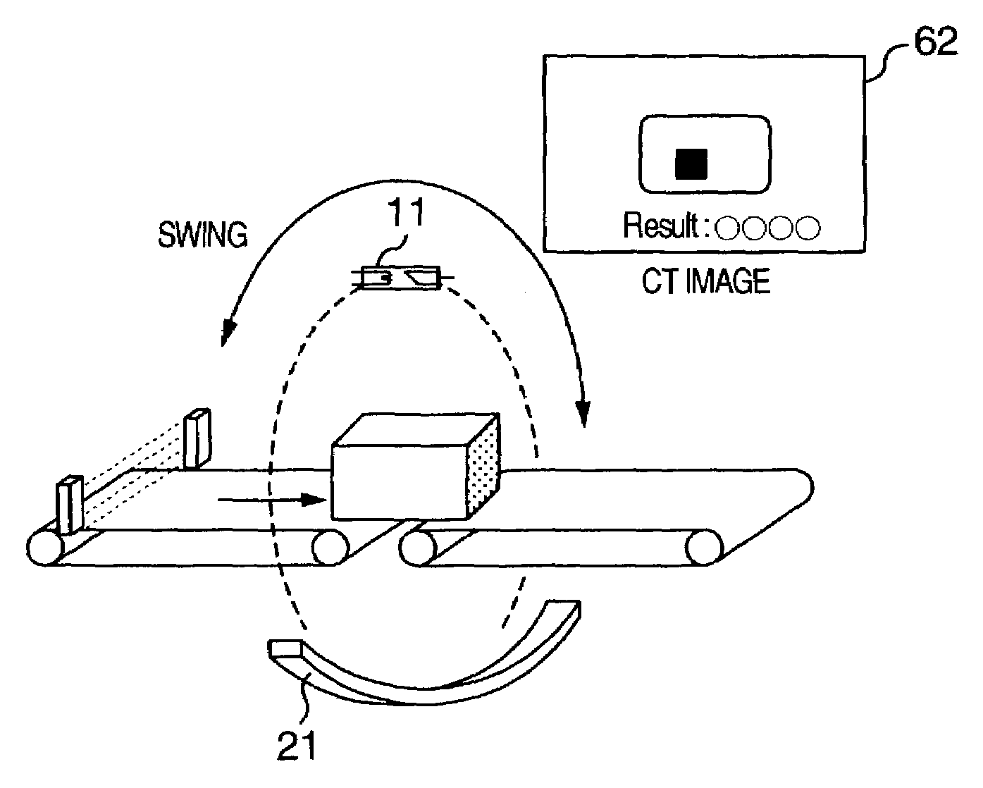
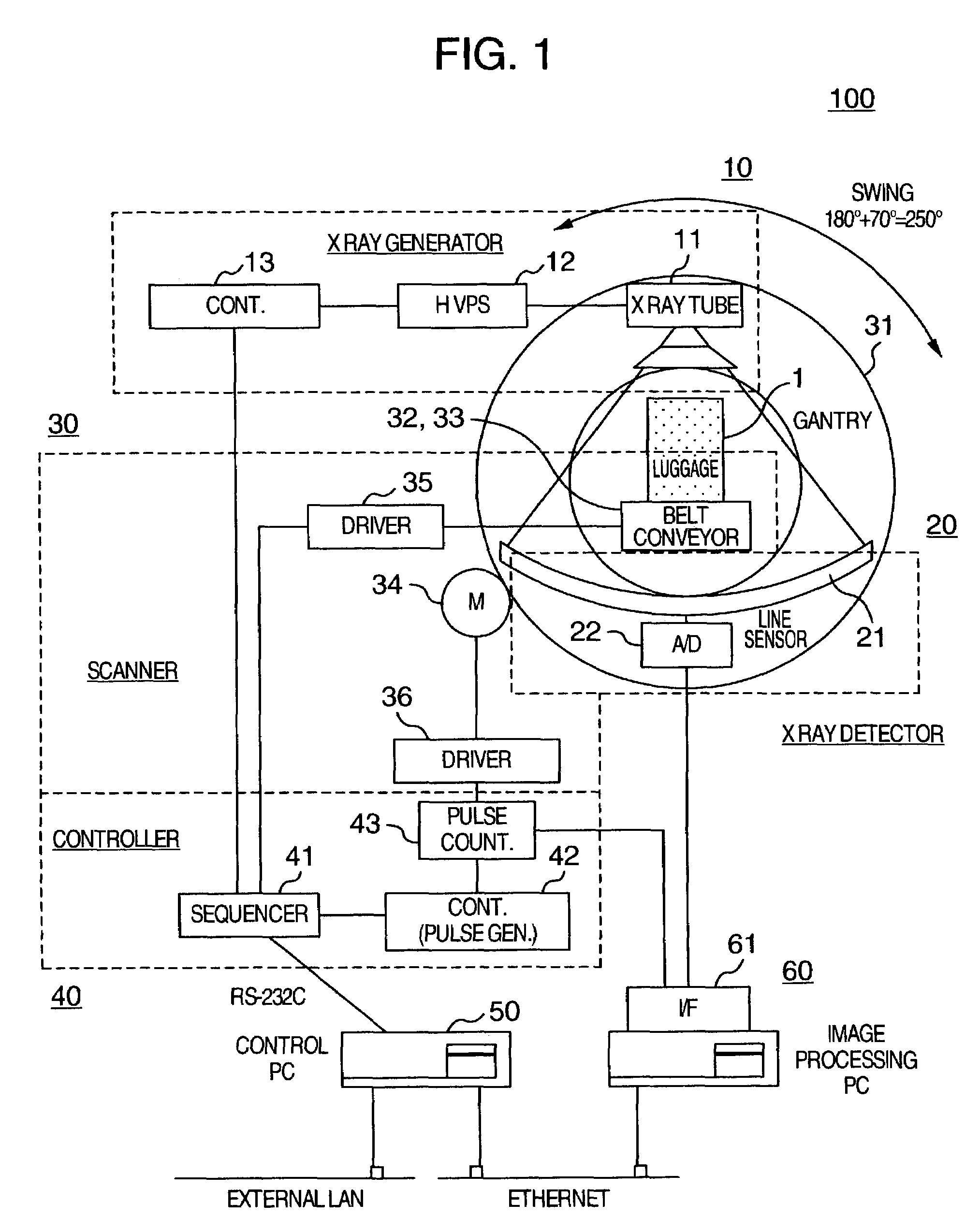
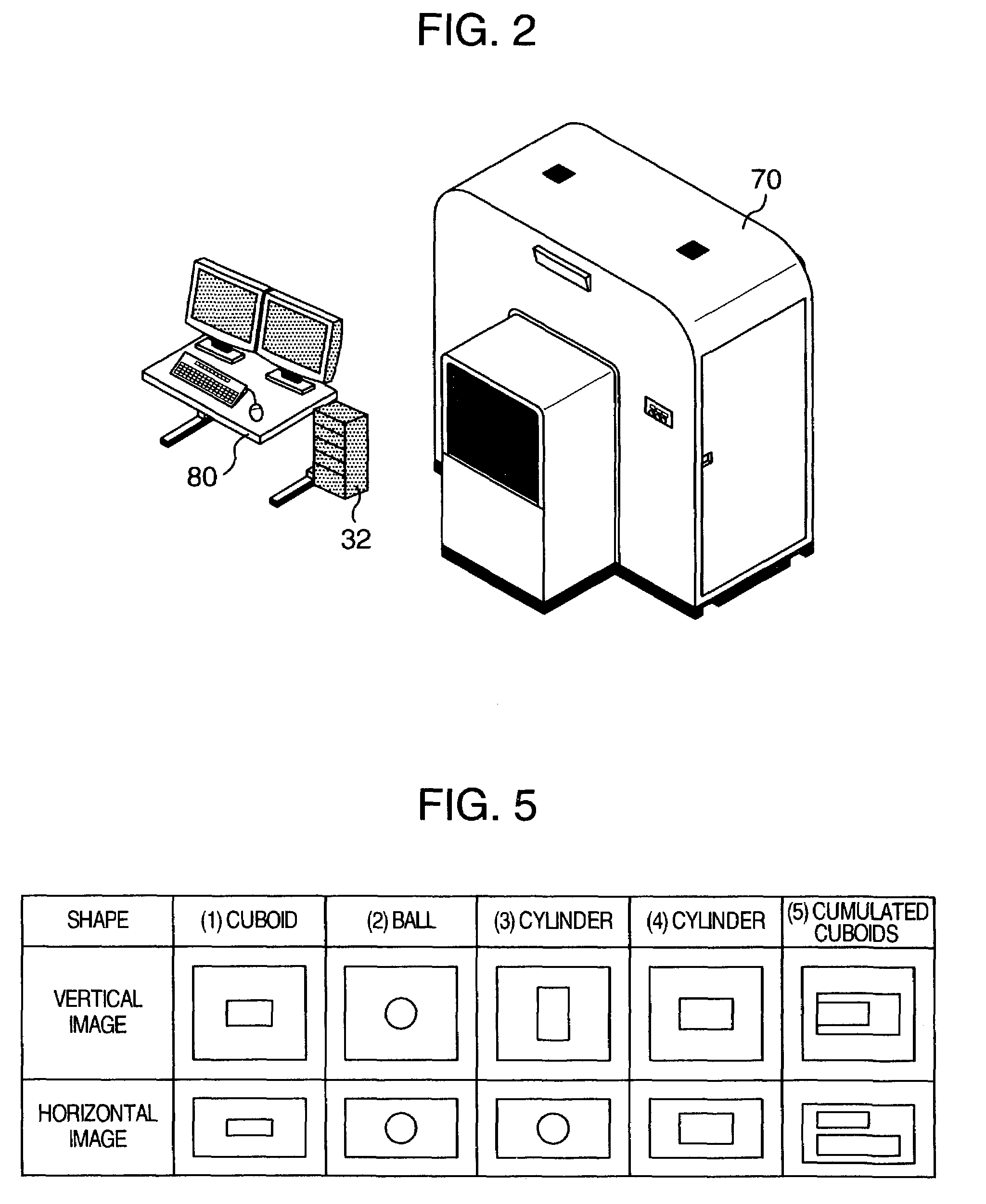
[0021]First, an embodiment of a threat detection apparatus according to the present invention will now be described with reference to FIGS. 1 to 7. FIG. 1 is a block diagram of a threat detection apparatus. FIG. 2 is an oblique exterior view of a threat detection apparatus. FIG. 3 is a diagram showing an operation flow a threat detection apparatus in an embodiment of the present invention. FIGS. 4A to 4C are oblique views and screen display diagrams showing operation of a threat detection apparatus. FIG. 5 is a diagram showing shapes judged on the basis of scan projection images obtained by changing the direction. FIG. 6 is a flow diagram showing a procedure for determining whether a threat is included in luggage on the basis of a scan projection image. FIG. 7 is a flow diagram showing a procedure for determining whether a threat is included in luggage on the basis of CT values.

[00...


PUM


Abstract

An image pickup unit is disposed so as to be able to obtain a scan projection image of an inspection subject from each of a vertical direction and a horizontal direction. An X-ray absorption coefficient of an object in the inspection subject is obtained from the vertical scan projection image and the horizontal scan projection image. It is determined whether there is a threat in the inspection subject on the basis of the X-ray absorption coefficient. Furthermore, a CT image is obtained by moving the image pickup unit around the inspection subject. It is determined whether there is a threat in the inspection subject, on the basis of the CT values of the CT image.

Description

BACKGROUND OF THE INVENTION[0001]The present invention relates to a threat detection apparatus and a threat detection method, and in particular to a threat detection apparatus and a threat detection method using X-rays.[0002]As for reference relating to the present invention, a threat detection apparatus that radiates X rays having two energy levels alternately is described in JP-A-2001-235434. A threat detection apparatus using a combination of scan projection and CT (Computed Tomography) is described in U.S. Pat. No. 5,182,764. In addition, a threat detection apparatus using a combination of scan projection and X-ray tubes (two tubes) differing in energy is described in U.S. Pat. No. 5,367,552.[0003]These threat detection apparatus utilize large-sized X-ray CTs of high speed. The threat detection apparatus can also detect explosives that are hard to detect in inspection apparatus using X-ray transmission seen in airports in Japan, and they are used mainly in large-sized airports i...

Claims


Application Information

Patent Timeline
IPC IPC(8): G01N23/083G01N23/04G01N23/06G01V5/00
CPCG01N23/046G01V5/005G01N2223/419
Inventor WAKAYAMA, KYOICHIROKOSHISHIBA, HIROYAOKADA, HIDEHIROHATTORI, YUKIYA
Owner HITACHI LTD
Why Eureka
Try Eureka