Radio location system measurement unit

a technology of radio location and measurement unit, which is applied in the direction of navigation instruments, instruments, wireless commuication services, etc., can solve the problems of inability to accurately measure ‘local’ signals, inability to place lmu antennas, and large delay of received signals, so as to reduce or eliminate the interference caused by local scattering and reliable and accurate measurements

Inactive Publication Date: 2007-08-21
CAMBRIDGE POSITIONING SYST LTD
View PDF15 Cites 41 Cited by
  • Summary
  • Abstract
  • Description
  • Claims
  • Application Information

AI Technical Summary

Benefits of technology

[0017]By connecting more than one coupling device to the LMU, a means is provided which allows the LMU to take reliable and accurate measurements of

Problems solved by technology

Investigations have shown that, in particular, it is difficult to place the LMU antenna so that all of the locally transmitted channels are received properly at the same time as receiving the signals from the distant BTSs.
Instead, the problem is caused by the interference effects from “local scatterers”, such as the ground and nearby buildings, which often cause the received signals to be delayed by substantial, variable, and unknown amounts.
This leads to the significant problems t

Method used


Image

  • Radio location system measurement unit
  • Radio location system measurement unit
  • Radio location system measurement unit

Examples


Embodiment Construction

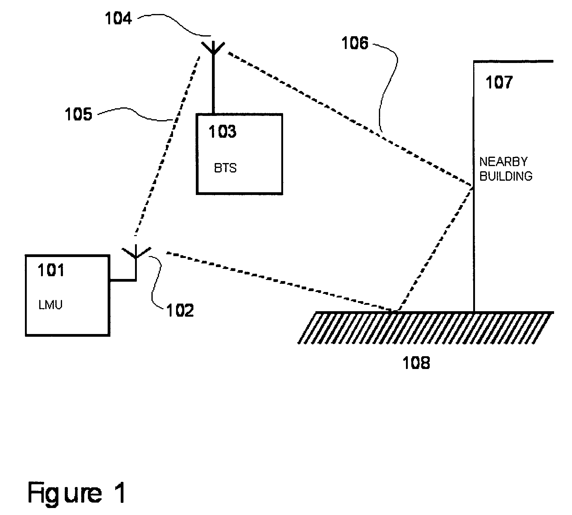
[0043]The problem associated with co-location of an LMU at a BTS site is caused by scattering and reflection from local objects such as buildings, trees, etc of the very bright signals radiated forward by the BTS antenna, as explained above. One such mechanism is illustrated in FIG. 1, which shows a BTS 103 connected to a transmitting antenna 104, and an LMU 101 connected to a receiving antenna 102. The transmitted signal 106 is reflected back to the LMU antenna 102 by the ‘corner reflector’ formed between a nearby building 107 and the ground 108. The reflected signal interferes with the signal 105 received directly from the back-lobe of the transmitting antenna 104 in a manner which is both unpredictable and variable. It would take just a half-wavelength change in the reflected signal path, for example, to transform from constructive to destructive interference at the LMU antenna, a few centimeters change in the path at GSM frequencies. The result is that the LMU reports a timing f...


PUM


Abstract

A location measurement unit 401 for a radio location measuring system has two or more coupling devices 404,405 for picking up the signals from a plurality of base transceiver stations (BTSs) of a cellular radio communication system. A switching device 510, is connected to the coupling devices, for switching between the signals picked up by the coupling devices and/or one/two or more receivers 510, 610-613 are connected to respective coupling devices, for receiving the signals picked up by the coupling devices. A processor 512, 614 is connected to the or each receiver, for processing the signals output by the receiver. A communications link 513, 615 is connected to the processor, for transferring the processed signals to a calculation node 514.

Description

BACKGROUND OF THE INVENTION[0001]1. Field of the Invention[0002]The present invention relates to radio location systems and, more particularly, to radio location measurement units used in radio location systems for locating the positions of cellular radio telephones (mobile stations).[0003]2. Description of the Related Art[0004]There are many systems known in the art by which the position of such a mobile station can be determined. Of particular relevance here are those systems for locating mobile stations in mobile telephone communications networks. One such method, known by its standardised acronym as E-OTD (Enhanced-Observed Time Difference) uses the relative timing offsets of signals received from the network transmitters by a mobile station, together with the relative timing offsets of the same signals received by a fixed receiver whose position is known. The second set of measurements by the fixed receiver is required since the transmissions may not be synchronised with respec...

Claims


Application Information

Patent Timeline
IPC IPC(8): H04Q7/20G01S5/10H04W64/00
CPCG01S5/10H04W64/00
Inventor DUFFETT-SMITH, PETER JAMESBRICE, JAMES PAULCLARKE, JOHN CHRISTOPHER
Owner CAMBRIDGE POSITIONING SYST LTD
Why Eureka
Try Eureka