
Method and device for determining the resistivity in a geological formation crossed by a cased well

a geological formation and resistivity technology, applied in seismology, instruments, waterlogging using reradiation, etc., can solve the problems of insufficient distance from the reference electrode, inability to place the reference electrode sufficiently far away from the casing, and inability to estimate the factor k

Inactive Publication Date: 2007-08-21
SCHLUMBERGER TECH CORP
View PDF5 Cites 8 Cited by
  • Summary
  • Abstract
  • Description
  • Claims
  • Application Information

AI Technical Summary

Benefits of technology

The patent text describes a method for determining the resistivity of a geological formation crossed by a cased well. The invention is based on the use of a tool that sends a current in the well and measures the voltage drop between two electrodes. The method is affected by the resistivity of the cement used to seal the well, which can change over time. The technical effect of the invention is to provide a reliable method for determining the resistivity of a geological formation in cased wells, which can help to monitor the behavior of the hydrocarbon deposits and optimize their exploitation.

Problems solved by technology

The factor k can only be estimated and its precision is often not very good.
Sometimes it is not possible to measure said voltage Vz, infinite with sufficient precision, the reference electrode cannot be placed sufficiently far away from the casing or the electrical contact between the reference electrode and the ground is not good quality.
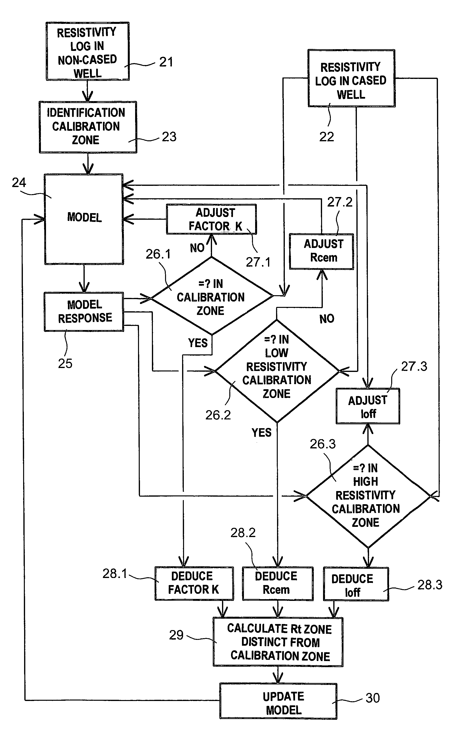
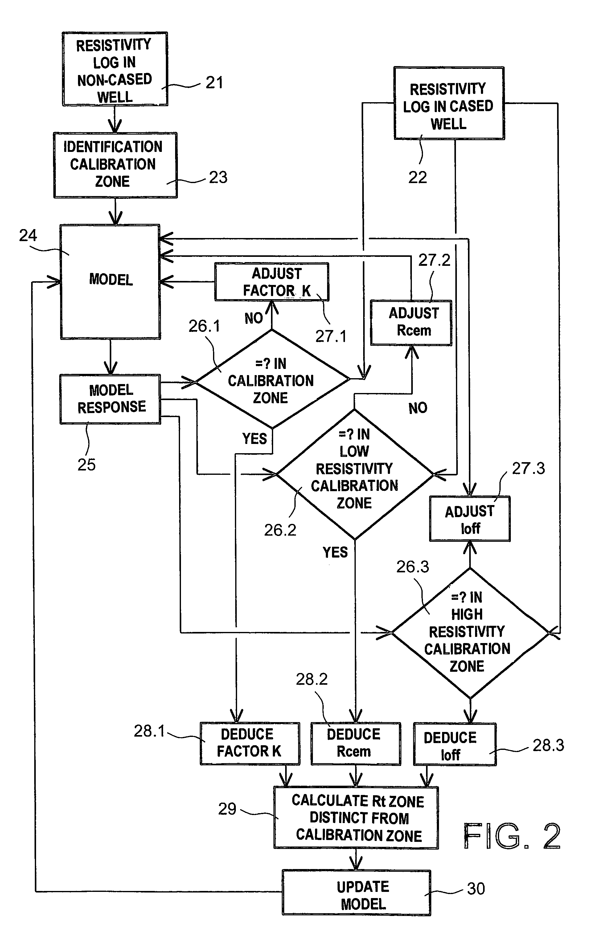
In addition to the aforementioned difficulties, it has been observed that the measurements of the current Ifor often suffer from a shift.
It is very difficult to estimate this offset current.
However, once it is in place, the cement is no longer directly accessible because it is behind the casing.
However, the use of charts does not make it possible to correct very efficiently the measured resistivity value of the formation in order to obtain the resistivity value of the formation.

Method used


Image

  • Method and device for determining the resistivity in a geological formation crossed by a cased well
  • Method and device for determining the resistivity in a geological formation crossed by a cased well
  • Method and device for determining the resistivity in a geological formation crossed by a cased well

Examples


Embodiment Construction

[0016]The aim of the present invention is to propose a method for determining the resistivity of a formation crossed by a cased well that leads to a much better precision than that obtained through traditional methods. The aim is to better evaluate the geometric factor k in order to improve the resistivity precision and to take account, in an effective manner, of the effect relating to the cement and the offset current.

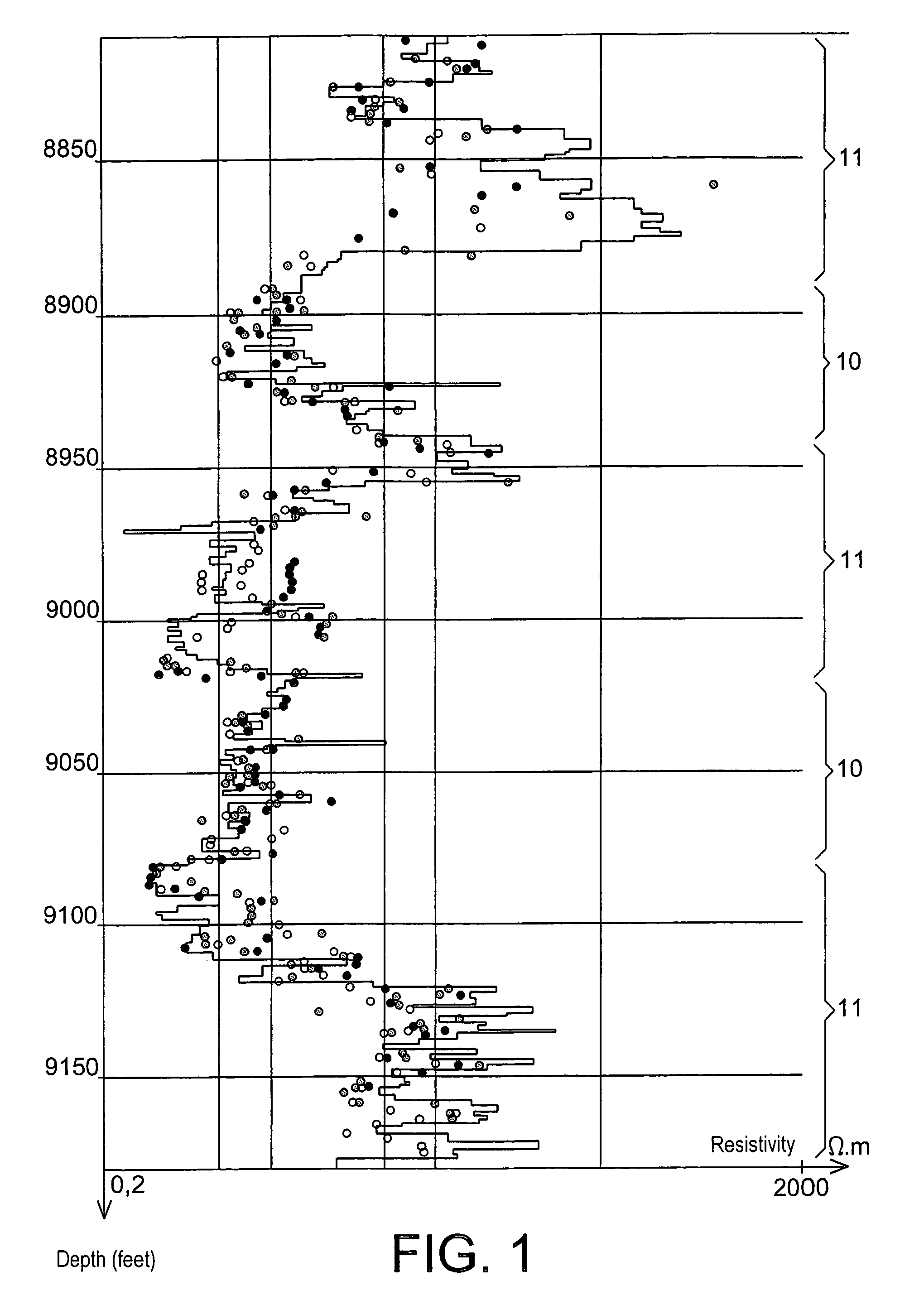
[0017]In order to achieve these aims, the present invention proposes carrying out at least one resistivity log in the cased well and using the results of at least one log in the non-cased well, carried out in the same well, in at least one zone of the formation in which the resistivity has not changed between the cased condition and non-cased condition in order to deduce the value of a geometric factor k conditioning the resistivity and in order to determine, by means of this geometric factor k and the log in the cased well, the resistivity in at least one zone differ...


PUM


Abstract

The invention concerns a method for determining the resistivity in a formation crossed by a cased well, in which one carries out at least one resistivity log in the cased well and one uses the results of at least one resistivity log in the non-cased well, carried out in the same well previously, in order to, in at least one zone (10) of the formation in which the resistivity has not changed between the cased and non-cased condition, deduce the value of a geometric factor k conditioning the resistivity and for determining, by means of said geometric factor k and the log in the cased well, the resistivity in at least one zone (11) different to the calibration zone, in which the resistivity has varied between the non-cased condition and the cased condition.

Description

TECHNICAL FIELD[0001]The invention concerns the determination of the resistivity in a geological formation crossed by a cased well.[0002]The importance of resistivity logs in oil exploration no longer needs to be demonstrated. It is known that the resistivity of a formation essentially depends on the fluid that it contains. A formation containing salty water, which is conductive, has a much lower resistivity than a formation full of hydrocarbons and, as a consequence, resistivity measurements have an indispensable value in locating hydrocarbon deposits. Resistivity logs have been very widely practised for a long time by means of electrode devices in non-cased wells, known as open holes. The presence in the well of a metallic casing that has an infinitesimal resistivity compared to the typical values for geological formations (around 2.10−7 Ω·m for a steel casing compared to 1 to 103 Ω·m for a formation) represents a barrier to sending electrical currents in the formations surroundin...

Claims


Application Information

Patent Timeline
Patent Type & Authority Patents(United States)
IPC IPC(8): G01V3/38G01V3/20
CPCG01V3/20
Inventor DUBOURG, ISABELLEFAIVRE, OLLIVIERROUAULT, GILLES
Owner SCHLUMBERGER TECH CORP
Learn More