
Method and apparatus for tunneling information

a tunneling information and tunneling technology, applied in the field of tunneling information methods and equipment, can solve the problems of increased overhead, shortcoming of conventional tunneling methodologies, and inability to expand the capacity of existing equipment, and achieve the effect of minimising additional overhead

Active Publication Date: 2007-08-21
CISCO TECH INC
View PDF22 Cites 33 Cited by
  • Summary
  • Abstract
  • Description
  • Claims
  • Application Information

AI Technical Summary

Benefits of technology

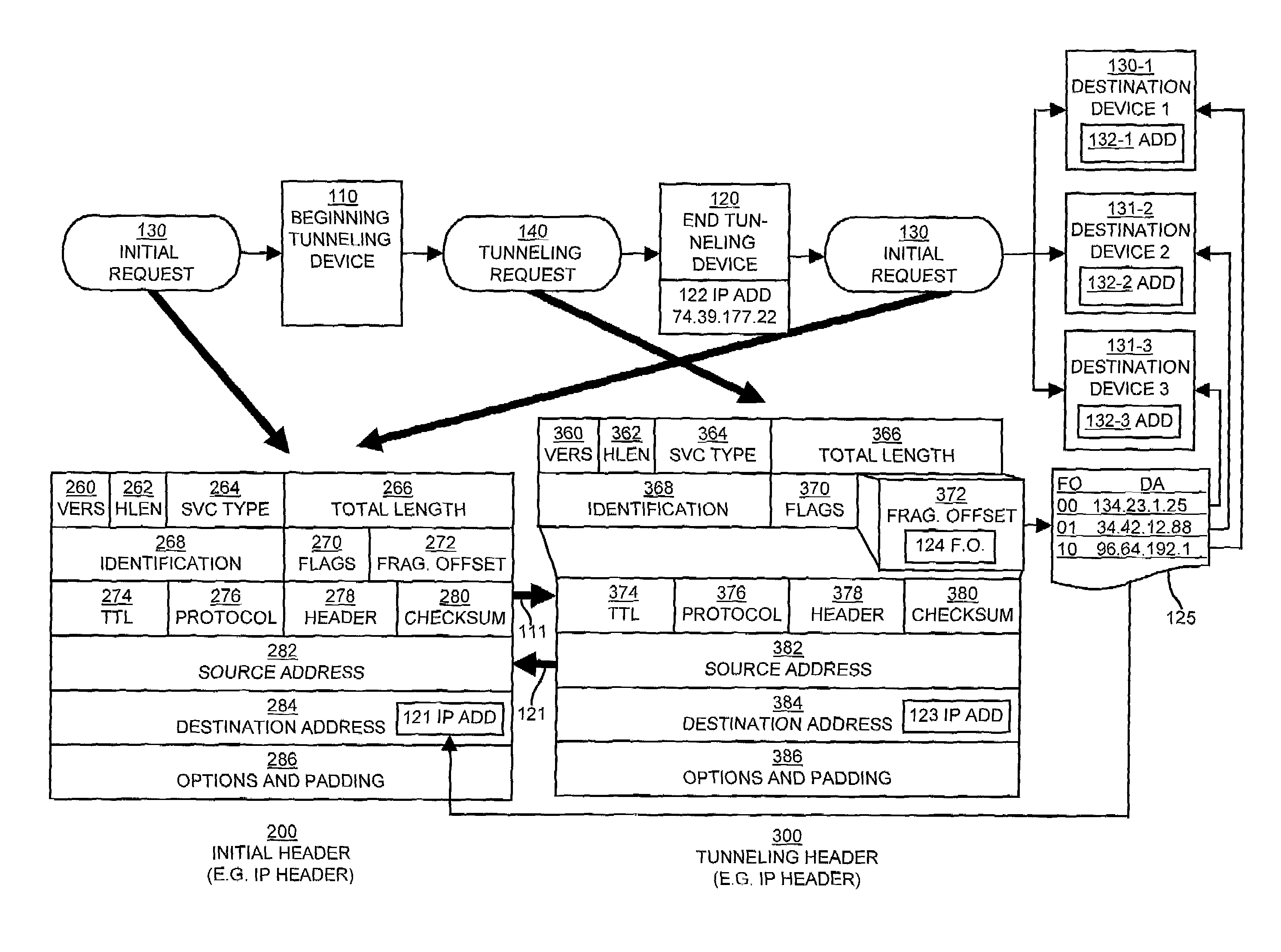
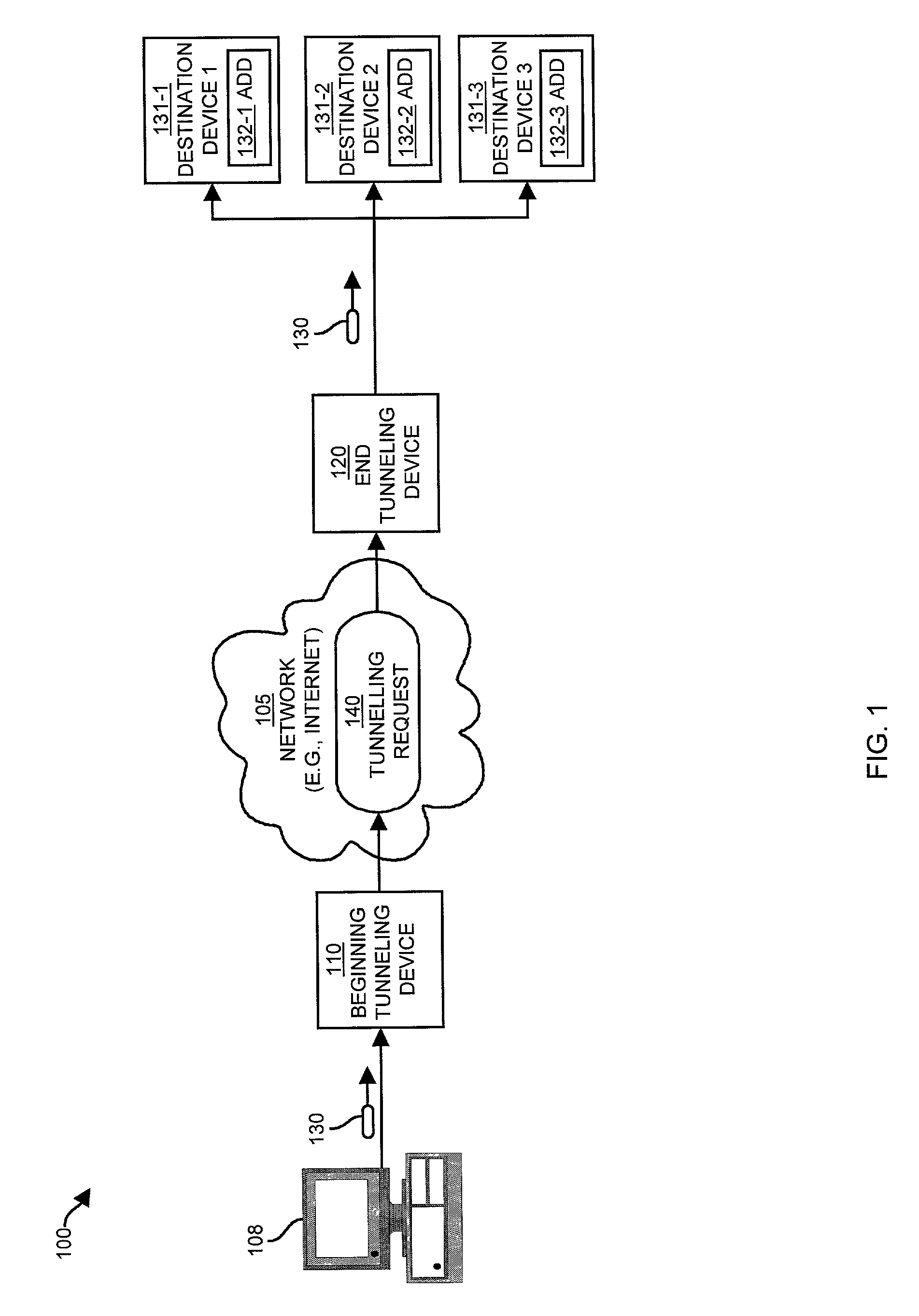
[0008]Embodiments of the invention are directed to techniques and mechanisms for transmission of content using an improved method of tunneling (e.g., tunneling of packets, etc.). The embodiments of the invention enable tunneling by modifying an initial request instead of encapsulating initial requests within even larger request packets. Unlike the conventional techniques and mechanisms for tunneling, the resulting tunneling request and data maintain their original size. Thus, there is no increase in the likelihood of fragmentation caused by tunneling and fragmentation need not occur at all. Accordingly, the embodiments of the invention permit tunneling without wasting additional bandwidth or adding overhead. A further advantage of the embodiments of the invention is that tunneling can be achieved without increasing the likelihood of discarded or re-transmitted segments that may occur due to packet segmentation and the further reduction of transmission capacity. Accordingly, the advantages of tunneling are possible without diminishing transmission capacity or expanding network facilities.
[0011]A significant advantage of the embodiments of the invention is a reduction of the processing resources that would otherwise be necessary using conventional tunneling. In addition to modifying fields and re-calculating an error correction code, as described in the steps above, conventional methods of tunneling require the management and calculation of packet sizes necessary to fit existing packets into the packets into which they are encapsulated, creation of new packets, assembly, disassembly, etc. Such tasks are significantly reduced or avoided all together according the embodiments of the invention, thereby achieving tunneling with lower consumption of system resources and little or no additional overhead.
[0022]In another embodiment, the initial request and the tunneling request are the same size. The embodiments of the invention allow for tunneling with minimal additional overhead.

Problems solved by technology

Computer networking involves an intricate, rapidly evolving complex of software and hardware systems, integrating different methodologies, techniques, processes, and protocols together.
Unfortunately, there are shortcomings to conventional tunneling methodologies.
The resulting additional processing represents an increase in overhead.
However, at other times the MTU limitation is related to the capacity of the equipment in place which is not able to be expanded.
Any increase in the size of packets increases the likelihood that fragmentation may become necessary.
The result is an increase of the information that must be transmitted due to overhead.
In addition to an increase in the use of bandwidth due to fragmentation, the occurrence of fragmentation consumes additional processing resources at both the originating and receiving ends of network hops.
This additional processing overhead results from the need to break-up packets and add additional new headers at the originating device and the need to eliminate headers and re-constitute fragmented segments into the original packet and notify the originating device of lost segments, if necessary, etc. at the receiving device.
An additional problem, related to fragmentation, is that a time limit may be enforced at the receiving device for reception of all packet needed to re-assemble any particular original packet into to its originally-transmitted form.
In high traffic situations, packet loss due to timing-out while waiting for the reception of packet fragments can be problematic, resulting in a further reduction of effective bandwidth.
Also, in situations requiring real-time data transfer, the extra overhead incurred from the use of conventional tunneling techniques can make real-time tunneling difficult if not impossible.

Method used


Image

  • Method and apparatus for tunneling information
  • Method and apparatus for tunneling information
  • Method and apparatus for tunneling information

Examples


Embodiment Construction

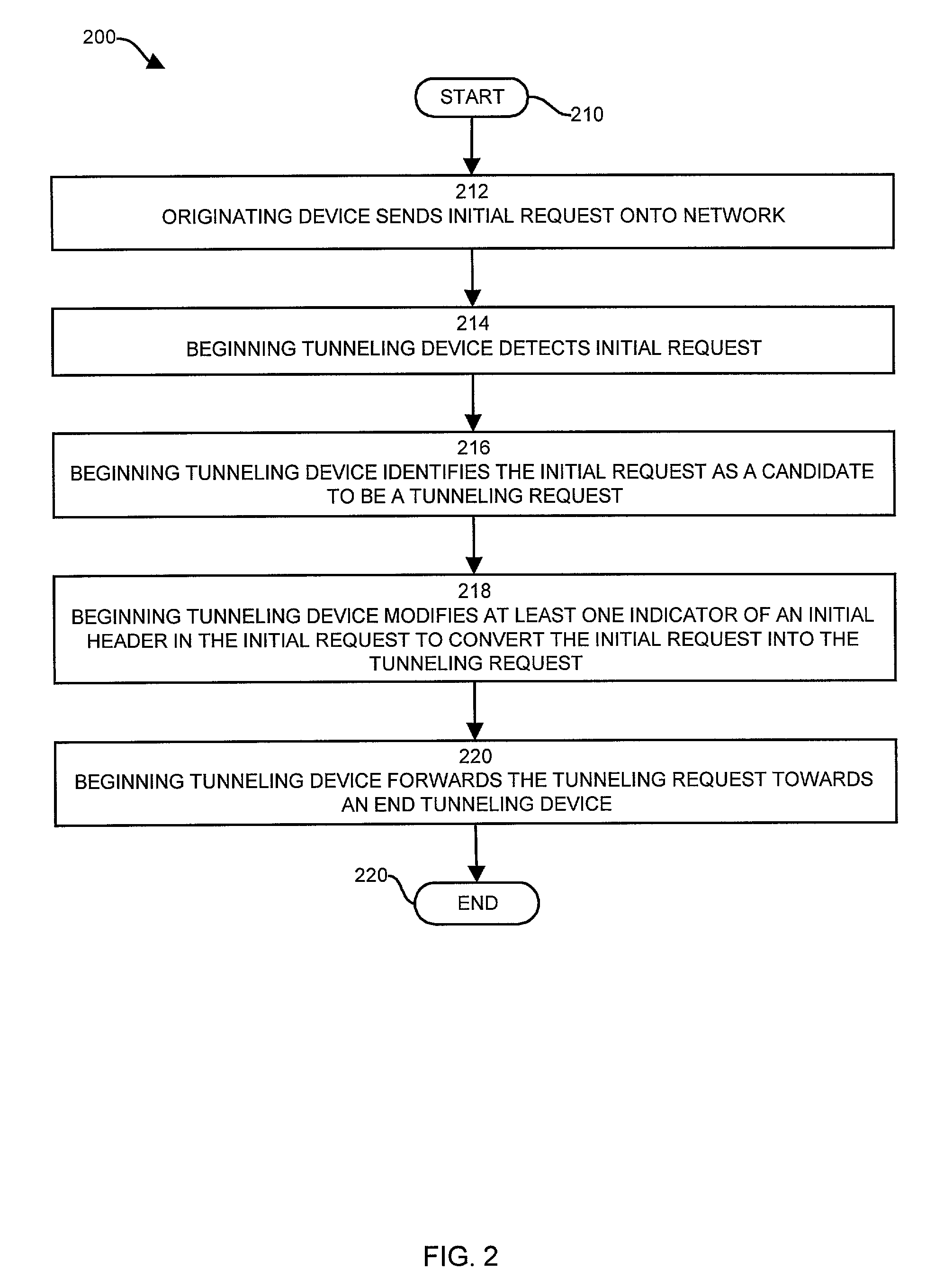
[0042]Embodiments of the invention are directed to techniques for identifying and transmitting tunneling requests, such as one or more packets by modifying the initial header of an initial request in order to change the initial request into a tunneling request. No creation or processing of additional headers or encapsulation of packets within other packets or headers is involved. In order to perform the tunneling, in one embodiment of the invention, a beginning tunneling device (e.g., a computer system, network device, switch, router, etc.) receives an initial request (e.g., a packet, communications message, etc.) from an originating device (e.g., a user computer or other network devices, etc.). Upon receipt of the initial request, the beginning tunneling device first identifies the initial request as a tunneling request, then modifies the initial header to create a tunneling header.

[0043]To do so, the beginning tunneling device replaces the IP protocol number indicating that the in...


PUM


Abstract

The invention is directed to techniques and mechanisms, used in a beginning tunneling device, for detecting an initial request, identifying the initial request as a candidate to be a tunneling request, modifying at least one indicator of an initial header in the initial request to convert the initial request into the tunneling request, and forwarding the tunneling request towards an end tunneling device. The invention is also directed to techniques and mechanisms in an end tunneling device for detecting a tunneling request, identifying the tunneling request as a candidate to be an initial request, modifying at least one indicator of a tunneling header in the tunneling request to convert the tunneling request into the initial request, and forwarding the initial request towards a destination device. The embodiments of the invention add little or no packet overhead.

Description

BACKGROUND OF THE INVENTION[0001]Computer networking involves an intricate, rapidly evolving complex of software and hardware systems, integrating different methodologies, techniques, processes, and protocols together. Various protocols provide standard methods which allow for communications between different components of such heterogeneous network systems. Network protocols have different operating characteristics. For example, UDP (user datagram protocol) is well suited to transporting certain multi-media files, Transmission Control Protocol (TCP) provides additional functions that ensure reliable transport of data to an intended destination, etc. Sometimes protocols are replaced with new versions of the protocols that can provide feature and operating characteristic enhancements. For example, version six of the Internet Protocol (IP) provides enhanced addressing and other features not available from earlier versions of the protocol.[0002]In order to accommodate different methods...

Claims


Application Information

Patent Timeline
IPC IPC(8): G06F15/16
CPCH04L69/16H04L69/166H04L69/161H04L69/22
Inventor LUECKENHOFF, BRUCE ARTHUR
Owner CISCO TECH INC
Learn More