
Multi-actuator pressure-based flow control system

a flow control system and actuator technology, applied in the direction of fluid couplings, servomotors, couplings, etc., can solve the problems of reducing the fine controllability of the actuator, and the pressure of the fluid moving the actuator may also rise abruptly

Active Publication Date: 2007-08-28
CATEPILLAR SARL +2
View PDF13 Cites 71 Cited by
  • Summary
  • Abstract
  • Description
  • Claims
  • Application Information

AI Technical Summary

Benefits of technology

This solution enhances controllability and predictability of actuator movements by scaling down fluid flow rates in response to pressure changes, improving efficiency by utilizing excess flow capacity and allowing extended modulation of actuator operations, while also enabling electronic tuning without hardware changes.

Problems solved by technology

However, when the movement of one of the actuators is restricted by an external load, the pressure of the fluid moving the actuator may rise abruptly.
Similarly, when movement of an actuator associated with a heavy work implement is initiated, the pressure of the fluid moving the actuator may also rise abruptly due to inertia of the heavy work implement.
These abrupt rises in pressure may reduce fine controllability of the actuators and produce actuator velocities that are unexpected and / or undesired.
Although the fluid pressure control system of the '023 patent may improve controllability and predictability of fluid actuator velocity, it may be inefficient and limited.
In particular, because the fluid pressure control system of the '023 patent improves controllability by relieving pressurized fluid to a tank, the work associated with pressurizing the relieved fluid may be lost, thereby reducing the efficiency of the hydraulic excavator.
Further, because any operation of the second actuator, regardless of magnitude, blocks feedback from the first actuator to the common pump, the pump of the '023 patent may be inefficiently operated during minor operations of the second actuator.
In addition, because the fluid pressure control system of the '023 patent is purely hydro-mechanical, tunability of the system may be limited.

Method used


Image

  • Multi-actuator pressure-based flow control system
  • Multi-actuator pressure-based flow control system
  • Multi-actuator pressure-based flow control system

Examples


Embodiment Construction

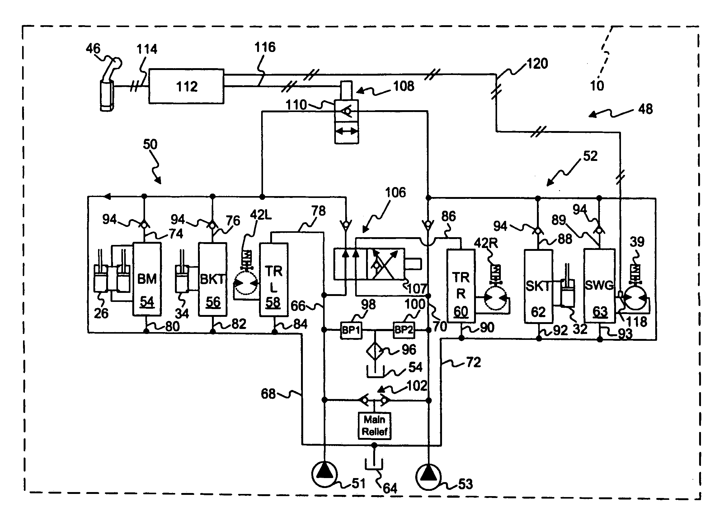
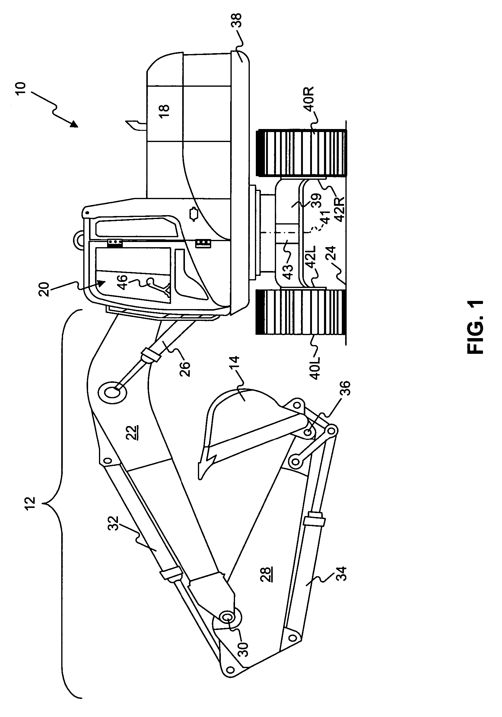
[0015]FIG. 1 illustrates an exemplary work machine 10 having multiple systems and components that cooperate to accomplish a task. Work machine 10 may embody a fixed or mobile machine that performs some type of operation associated with an industry such as mining, construction, farming, transportation, or any other industry known in the art. For example, work machine 10 may be an earth moving machine such as an excavator, a dozer, a loader, a backhoe, a motor grader, a haul truck, or any other earth moving machine. Work machine 10 may include an implement system 12 configured to move a work tool 14, a drive system 16 for propelling work machine 10, a power source 18 that provides power to implement system 12 and drive system 16, and an operator station 20 for operator control of implement and drive systems 12, 16.

[0016]Implement system 12 may include a linkage structure moved by fluid actuators to position and operate work tool 14. Specifically, implement system 12 may include a boom...


PUM


Abstract

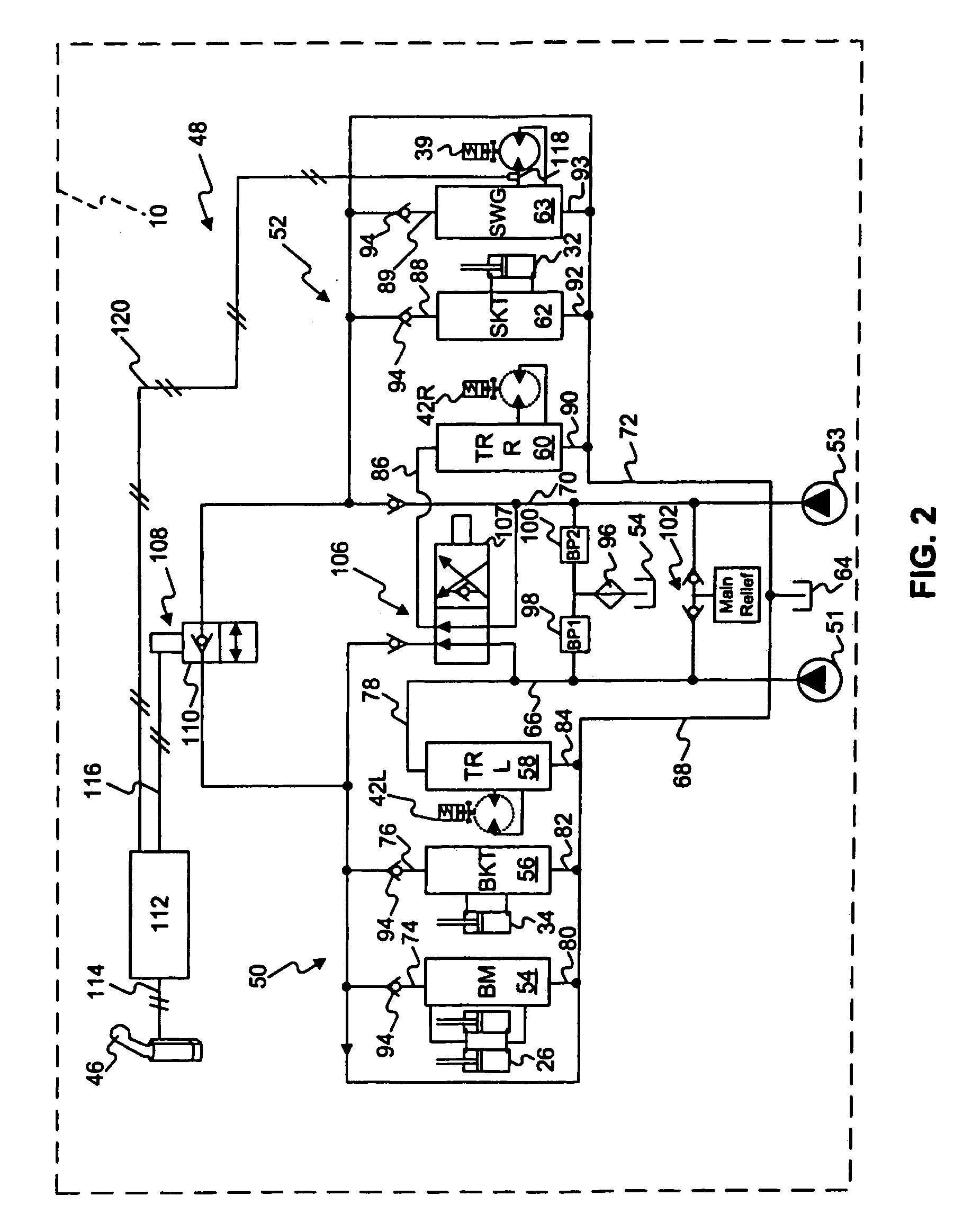
A hydraulic control system for a work machine is disclosed. The hydraulic control system has a fluid actuator, a supply of pressurized fluid, and a control valve movable to selectively pass pressurized fluid to the fluid actuator. The hydraulic control system also has a sensor configured to sense the pressure of the pressurized fluid passed to the fluid actuator and a controller in communication with the control valve and the sensor. The controller is configured to receive an input indicative of a desired velocity of the fluid actuator and to determine a fluid flow rate corresponding to the desired velocity. The controller is also configured to determine a ratio of the sensed pressure to a stall pressure of the supply and to scale down the determined flow rate an amount based on the determined ratio. The controller is further configured to move the control valve an amount corresponding to the scaled down flow rate.

Description

TECHNICAL FIELD [0001]The present disclosure relates generally to a multi-actuator flow control system, and more particularly, to a multi-actuator flow control system that is pressure based.BACKGROUND [0002]Work machines such as, for example, excavators, loaders, dozers, motor graders, and other types of heavy machinery use multiple actuators supplied with hydraulic fluid from a common pump on the work machine to accomplish a variety of tasks. These actuators are typically velocity controlled based on an actuation position of one or more operator interface devices. For example, an operator interface device such as a joystick, a pedal, or any other suitable operator interface device may be movable to generate a signal indicative of a desired velocity of an associated hydraulic actuator. When an operator moves the interface device, the operator expects the hydraulic actuator to move at a corresponding predetermined velocity. However, when the movement of one of the actuators is restri...

Claims


Application Information

Patent Timeline
Patent Type & Authority Patents(United States)
IPC IPC(8): F15B11/16F15B21/08E02F9/22
CPCE02F9/2203E02F9/2228E02F9/226E02F9/2292F15B11/163F16D31/02F15B2211/20576F15B2211/6306F15B2211/6346F15B2211/665F15B2211/7053F15B2211/7058
Inventor EGELJA, ALEKSANDAR M.TOZAWA, SHOJIVERKUILEN, MICHAEL T.
Owner CATEPILLAR SARL
Learn More