
Miniature flashlight having replaceable battery pack and multiple operating modes

Inactive Publication Date: 2007-08-28
ARMAMENT SYST & PROCEDURES
View PDF5 Cites 5 Cited by
  • Summary
  • Abstract
  • Description
  • Claims
  • Application Information

AI Technical Summary

Benefits of technology

[0011]A pair of side covers are retained on opposite sides of the battery frame by side shell members so that outer surfaces of the side covers are exposed for receiving indicia thereon. The switch push button is received through a suitable opening in the side cover adjacent the printed circuit board so as to enable an operator to actuate the push button to effect momentary or continuous interconnection of the LED to the battery pack without either lead of the LED physically contacting the battery pack. The battery frame protects the modular battery pack and positions it in precise relation to the light source and the switch slide plate. The battery frame also cushions the internal elements from the adverse affects of any shock the flashlight might be subjected to.
[0020]One of the primary objects of the present invention to provide a flashlight that is of a small, relatively flat and compact size, is exceptionally durable and reliable, and utilizes a battery frame to support and protect a light source, preferably a high-intensity LED, a power source in the form of a replaceable modular battery pack, and a switch mechanism that is operative to close a circuit including the battery pack and LED to enable momentary or continuous energizing of the LED in a number of operating modes without the LED leads physically contacting batteries of the battery pack.

Problems solved by technology

The Micro Light has a number of disadvantages in that it lacks the durability required for a miniature flashlight, and also lacks an internal structure for protecting and securing the batteries and LED, having only the hard plastic outer shell to protect the internal components.
The Micro Light may therefore be adversely affected when subjected to shock.
Further, the use of screws to assemble the outer shell halves together increases the time and cost of assembly.
In addition, the Micro Light has a very small keyring hole that is not well adapted for securing the flashlight to a keychain, or to otherwise readily attach and release the flashlight from one's clothing.
Another major drawback with the Micro Light is that it uses either a slide switch or pressure switch which upon activation brings both leads of the LED into direct engagement with the batteries.
This results in increased fatigue on the leads of the LED and ultimately results in failure.
Moreover, because of its external shape and hard plastic outer shell construction, the Micro Light is not suitable for receiving markings or engravings on the outside surfaces thereof In many instances it is desirable to color code the exterior of the flashlight, or to provide engravings, markings, or other indicia on the exterior surface.
The Micro Light is not well suited for any such color coding or desired markings or engravings.

Method used


Image

  • Miniature flashlight having replaceable battery pack and multiple operating modes
  • Miniature flashlight having replaceable battery pack and multiple operating modes
  • Miniature flashlight having replaceable battery pack and multiple operating modes

Examples


Embodiment Construction

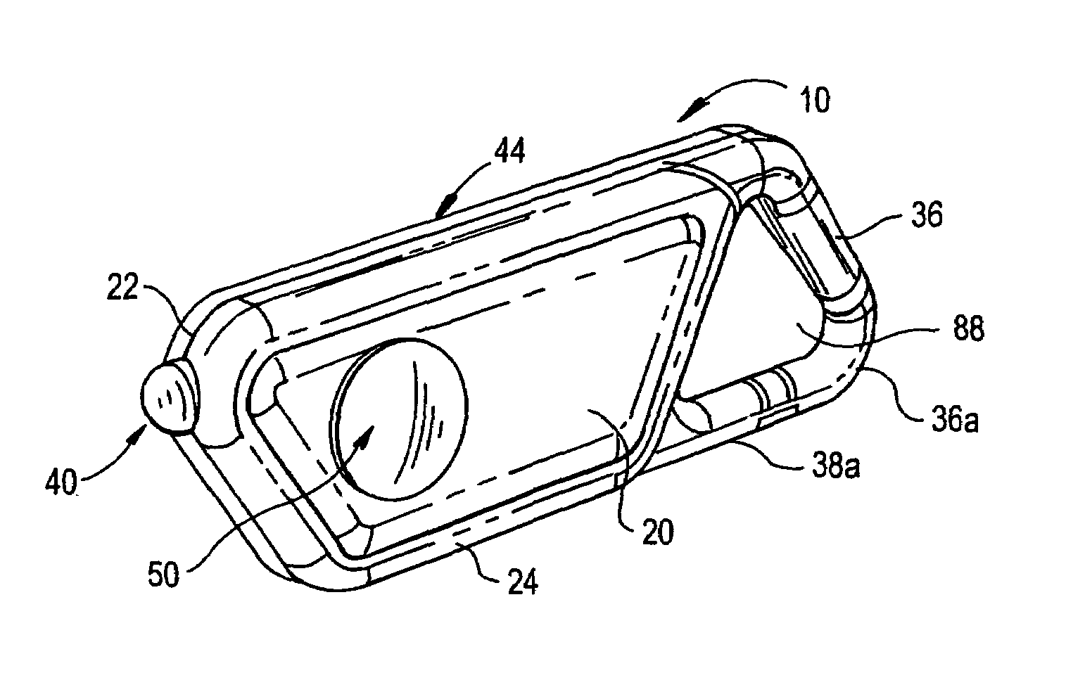
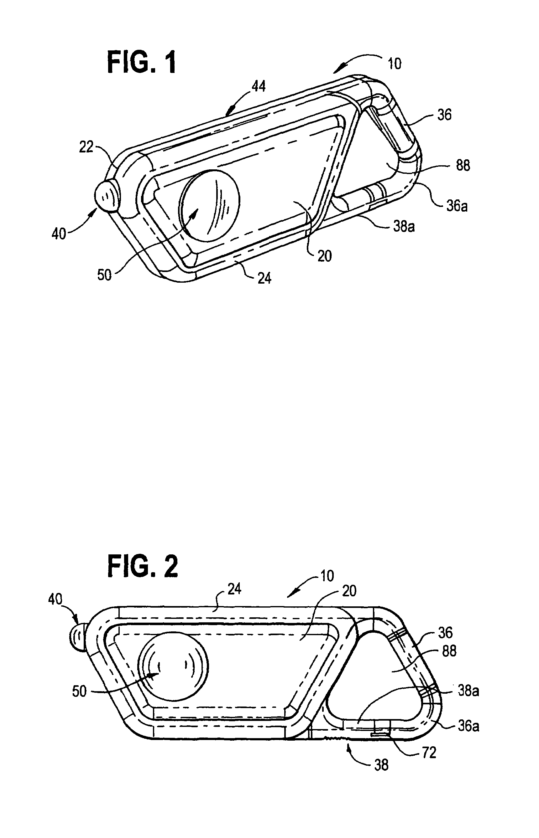
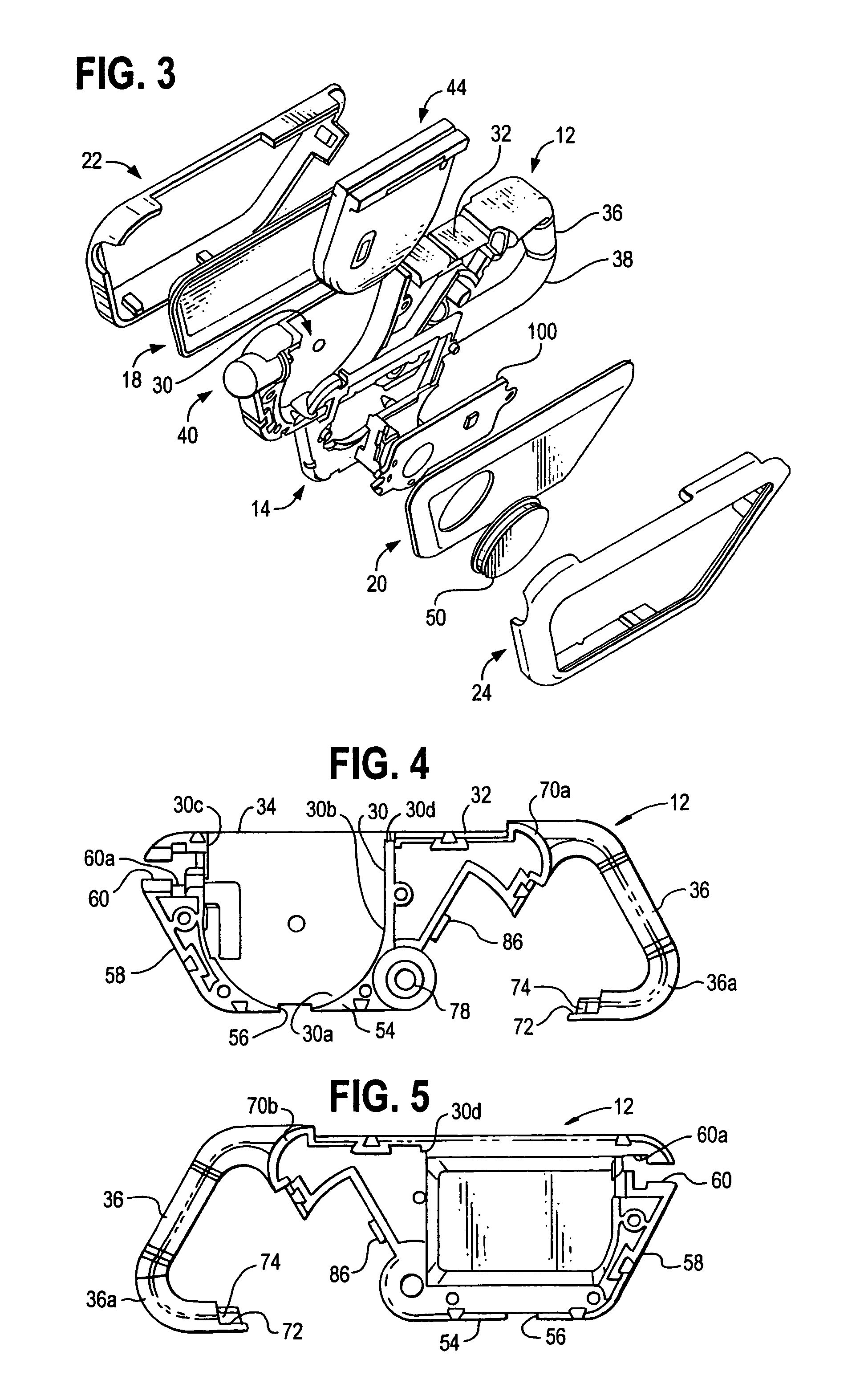
[0054]Referring now to the drawings, and in particular to FIGS. 1-3, a miniature handheld flashlight made in accordance with the present invention is indicated generally at 10. Very generally, and as illustrated in the exploded view of FIG. 3, the flashlight 10 has a housing which, in the preferred embodiment, includes a battery frame 12 that supports a high intensity light source 40 at a front end of the battery frame and to which is attached a printed circuit board (PCB) plate 14 and attached PCB 100, side covers 18 and 20, and open centered side shells or frames 22 and 24 that retain the side covers against opposite side of the battery frame. The battery frame 12, PCB plate 14 and PCB 100 cooperate to define a recess or chamber 30 that extends into the battery frame and opens outwardly of an edge surface 32 of the battery frame to facilitate sliding insertion of a replaceable battery pack as indicated at 44.

[0055]A keyring extension 36 is formed on an end of the battery frame 12 ...


PUM


Abstract

A method and apparatus are provided for operating a flashlight using a light emitting diode as a primary light source. The method includes the steps of activating the light emitting diode as the primary light source of the flashlight under one of a plurality of different operating modes and selecting the operating mode using a momentary contact disposed on an outer surface of the flashlight. In the disclosed embodiments, the flashlight takes the form of a relatively small size, generally flat housing having metallic side panels that may be of various colors and have indicia printed on them. The housing has an integral keyring extension enabling an article to be attached to the flashlight or for the flashlight to be attached to other articles, such as the clothing of a user.

Description

[0001]This application is a continuation-in-part of U.S. application Ser. No. 10 / 140,275 filed on May 6, 2002, entitled Miniature Flashlight Having Replaceable Battery Pack And Multiple Operating Modes, and currently pending.FIELD OF INVENTION[0002]The present invention relates generally to flashlights, and more particularly to a miniature flashlight utilizing a light emitting diode (“LED”) light source and a replaceable modular battery pack operative in response to predetermined switch actuation to effect momentary, selective signaling or continuous energizing of the LED.BACKGROUND OF THE INVENTION[0003]Conventional general-purpose flashlights are well known and find wide application by both law enforcement personnel and civilians. For example, flashlights are often used by law enforcement personnel during traffic stops to illuminate the interior of a stopped vehicle or to complete a police report in the dark. They are also used to facilitate searches of poorly lit areas and may be...

Claims


Application Information

Patent Timeline
IPC IPC(8): F21L4/04A44B15/00F21L4/00F21V15/01F21V23/04
CPCA44B15/005F21L4/005F21V15/01F21V23/0414H05B37/02F21Y2101/02F21Y2115/10H05B47/17
Inventor PARSONS, KEVIN L.REEVES, W. CLAY
Owner ARMAMENT SYST & PROCEDURES
Learn More