Novel dynamic stabilization machine tool

A dynamic and stable machine tool technology, applied in the processing of models, decorative arts, engraving, etc., can solve the problems of inconvenient engraving, lower processing efficiency, inconvenient use, etc., and achieve the effect of simple structure, meeting the needs of use, and convenient use

Inactive Publication Date: 2018-11-13
郭超杰
View PDF0 Cites 0 Cited by
  • Summary
  • Abstract
  • Description
  • Claims
  • Application Information

AI Technical Summary

Problems solved by technology

[0002] With the continuous development of industrial technology, some dynamic machine tools for workpiece engraving are widely used in industrial production. The workpiece needs to be clamped and fixed during the engraving process. However, after the traditional dynamic machine tool clamps the workpiece, Its fixed position is limited. Therefore, o

Method used


Image

  • Novel dynamic stabilization machine tool
  • Novel dynamic stabilization machine tool
  • Novel dynamic stabilization machine tool

Examples


Embodiment Construction

[0022] All the features disclosed in this specification, or all disclosed methods or steps in the process, except for mutually exclusive features and / or steps, can be combined in any manner.

[0023] Any feature disclosed in this specification (including any appended claims, abstract and drawings), unless specifically stated, can be replaced by other equivalent or equivalent alternative features. That is, unless otherwise stated, each feature is just one example of a series of equivalent or similar features.

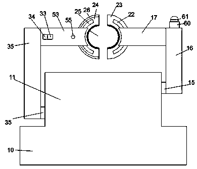
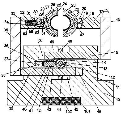
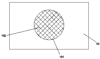
[0024] Such as Figure 1-3 As shown, a new type of dynamically stabilized machine tool of the present invention includes a base 10, a counterweight groove 101 is provided in the bottom end surface of the base 10, a counterweight 102 is fixed in the counterweight groove 101, and the base 10 A base 11 is fixed at the upper end. The base 11 is provided with a first chute 46 with a left mouth and a second chute 50 with a right mouth and located above the first chute 46. A first...


PUM


Abstract

The invention discloses a novel dynamic stabilization machine tool. The machine tool comprises a base, a base table is fixedly arranged at the upper end of the base, a first sliding groove with a opening part facing leftward is arranged in the base table, and a second sliding groove with the opening part facing rightwards and located above the first sliding groove is arranged in the base table, acommunicating first through-connection groove is formed between the first sliding groove and the second sliding groove, and a first sliding block and a second sliding block are installed in the firstsliding groove and the second sliding groove in a sliding mode respectively; and the opposite end faces of the first sliding block and the second sliding block are respectively provided with a first tooth-shaped strip and a second tooth-shaped strip, a first tooth-shaped wheel which is connected with the first tooth-shaped strip and the second tooth-shaped strip in a matched mode is rotatably installed in the first through-connection groove through a first rotating rod; and the front end of the first rotary rod is rotationally installed in the front end wall of the first through-connection groove, the rear end of the first rotary rod is in power connection with an electric machine which is fixedly installed in the rear end wall of the first through-connection groove.

Description

Technical field [0001] The invention relates to the field of dynamic machine tool equipment, in particular to a new type of dynamic stable machine tool. Background technique [0002] With the continuous development of industrial technology, some dynamic machine tools for engraving workpieces are widely used in industrial production. Workpieces need to be clamped and fixed during the engraving process. However, after the traditional dynamic machine tool equipment clamps the workpiece, The fixed position is limited. Therefore, once the clamping position of the workpiece surface is not accurate enough, it will cause great inconvenience to the carving. If you need to adjust the carving position again, you need to open the clamping part and perform the clamping operation again. , Its use is very inconvenient and will greatly reduce the processing efficiency. Summary of the invention [0003] The purpose of the present invention is to provide a new dynamically stable machine tool and a...

Claims


Application Information

Patent Timeline
IPC IPC(8): B44B1/06B44B3/06
CPCB44B1/06B44B3/065
Inventor 郭超杰
Owner 郭超杰
Why Eureka
Try Eureka