
Electric motor and generator component having a plurality of windings made from a plurality of individually conductive wires

a technology of electrically conductive wires and windings, which is applied in the direction of dynamo-electric machines, electrical apparatus, and magnetic circuit shapes/forms/construction, etc., can solve the problems of difficult or impractical manufacturing of motors and generators having a large cross-sectional area per turn of windings, difficult to maintain several parallel conductors together during manufacturing or winding process, and difficult to manipulate and form large cross-section conductors, etc., to achieve simpl

Inactive Publication Date: 2007-08-28
HAMILTON SUNDSTRAND CORP
View PDF14 Cites 23 Cited by
  • Summary
  • Abstract
  • Description
  • Claims
  • Application Information

AI Technical Summary

Benefits of technology

[0009]In general terms, this invention is an electric motor or generator assembly having a component with a plurality of windings that each comprise a relatively large number of individual conductors twisted together. The individual conductors provide a cross section as large as required but allows for easy handling and manipulation of the wire set, which makes the manufacturing process simpler and more economical.
[0013]The inventive arrangement and approach provides an improved motor or generator assembly and increased manufacturing economies because the ability to handle the wires required to make the windings of desired cross section is simplified compared to prior attempts. This winding configuration can be either hand or machine wound due to the reduced number of wire sets. In one example, an in-slot winding technique is used, although other winding techniques may also be used.

Problems solved by technology

Motors and generators having a large cross sectional area per turn of the winding are difficult or impractical to manufacture using conventional approaches.
Large cross-section conductors, for example, are difficult to manipulate and form.
A disadvantage of using a plurality of conductors in parallel is that it can be difficult to maintain the several parallel conductors together during the manufacturing or winding process.

Method used


Image

  • Electric motor and generator component having a plurality of windings made from a plurality of individually conductive wires
  • Electric motor and generator component having a plurality of windings made from a plurality of individually conductive wires

Examples


Embodiment Construction

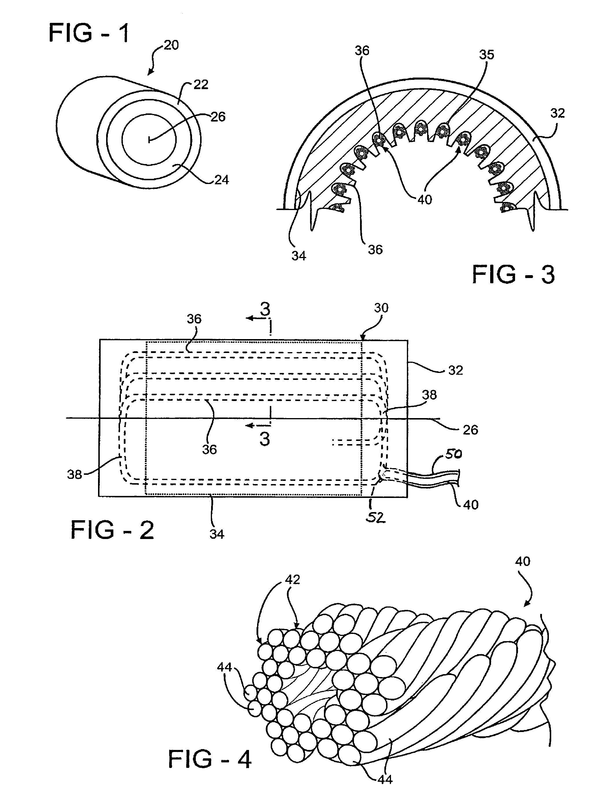
[0019]FIG. 1 schematically illustrates an assembly 20 that may be an electric motor, generator or both. The assembly 20 includes a first portion 22 and a second portion 24. One of the portions 22 or 24 is supported to be rotational relative to the other about an axis 26 of the motor assembly. The manner of powering an electric motor or obtaining power from a generator is known.

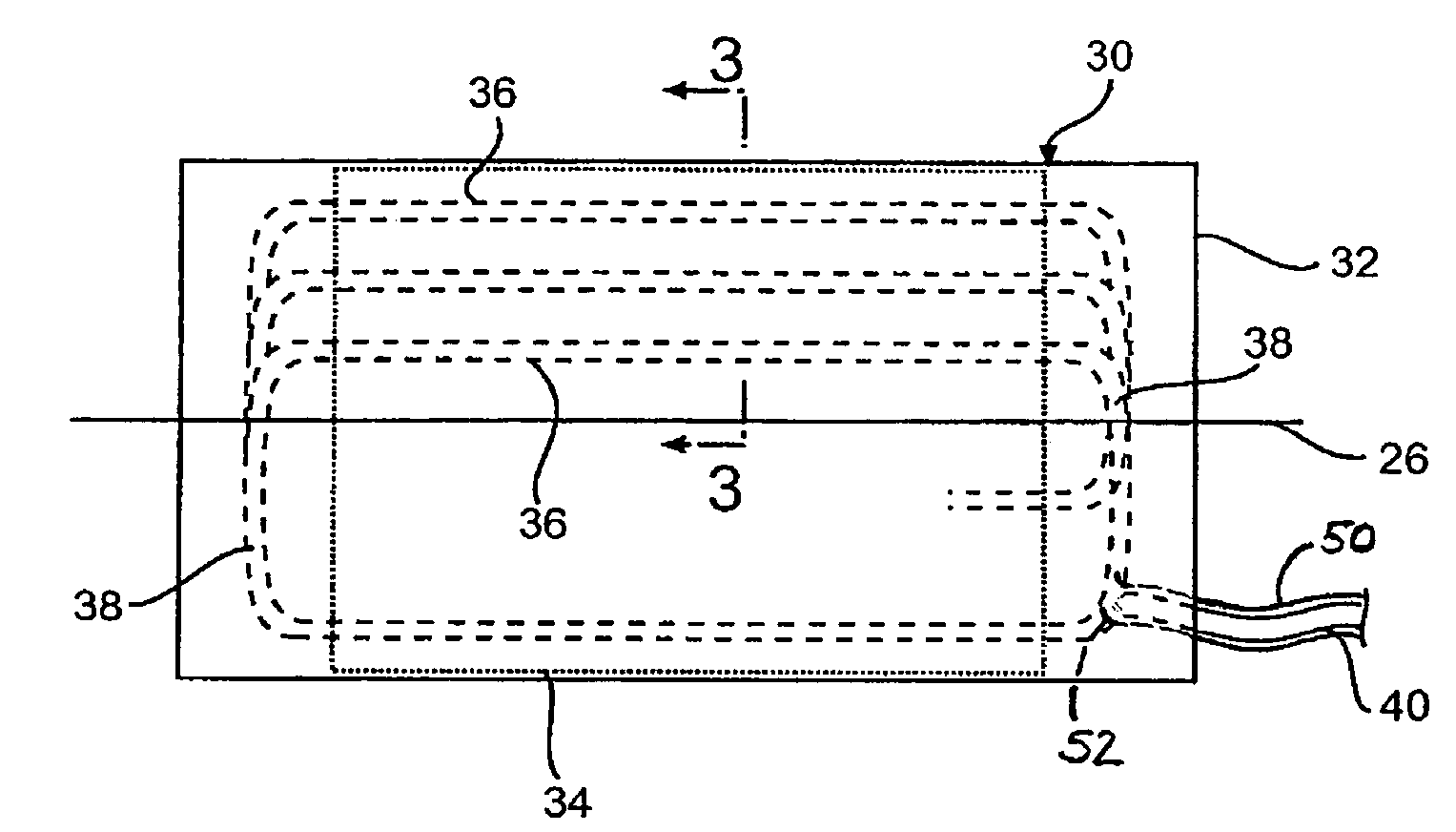
[0020]FIG. 2 schematically illustrates a stator motor and generator component 30 designed according to this invention. A stator core 34 includes a plurality of longitudinally extending slots 35 (best seen in FIG. 3). The stator core 34 can be formed in a conventionally known manner using a plurality of sheets or laminations of metal material. The channels or grooves 35 support a plurality of electrically conductive windings 36 that have a plurality of individual conductors that collectively establish a cross sectional dimension sufficient to meet the needs of a particular situation. The windings 36 extend thro...


PUM


Abstract

An electric motor or generator assembly includes a component, such as a stator, having a plurality of windings. A wire set including a plurality of individually conductive wires twisted together is manipulated within a core to establish the desired number of windings having the desired cross sectional area. In one example, a plurality of such wire sets are manipulated simultaneously to establish the windings. Litz wire is one example type of wire set that is useful in an assembly designed according to this invention. There are more than 100 individual wires within each winding according to one example stator designed according to this invention.

Description

BACKGROUND OF THE INVENTION[0001]1. Field of the Invention[0002]This invention generally relates to electric motors and generators. More particularly, this invention relates to electric motor and generator components having electrically conductive windings with large cross sections.[0003]2. Description of the Prior Art[0004]Electric motors and generators are well known and in widespread use. There are a variety of applications for electric motors and generators. Depending on the application, different motor and generator characteristics are required.[0005]In conventional electric motors and generators, stator windings are constructed by winding coils of conductors. For many applications the coils are constructed using one to three single strand conductors in parallel in order to provide the desired characteristics. For higher speed or low voltage applications, however, the electromagnetic design often requires a coil that has a lower number of turns and a proportionally increased cr...

Claims


Application Information

Patent Timeline
Patent Type & Authority Patents(United States)
IPC IPC(8): H02K1/00H02K3/14
CPCH02K3/14
Inventor WORLEY, ANDREW C.KINTZ, JR., LAWRENCE J.DICKES, GARYSHAH, MAHESHWALLEN, BRUCE J.
Owner HAMILTON SUNDSTRAND CORP
Learn More