Image lens array

a technology of image lens array and image, which is applied in the field of image lens array, can solve the problems of increasing both the sensitivity of the optical system and the stray light of the optical system, complicating the design process, and reducing the size of the image lens array of the present invention. , to achieve the effect of improving resolution and reducing the size of the image lens array of the present invention

Active Publication Date: 2007-08-28
LARGAN PRECISION
View PDF4 Cites 37 Cited by
  • Summary
  • Abstract
  • Description
  • Claims
  • Application Information

AI Technical Summary

Benefits of technology

[0010]The primary objective of the present invention is to provide a minimized image lens array comprising a first positive meniscus plastic lens with a convex surface facing forward, a second negative meniscus plastic lens with a concave surface facing forward, a third positive meniscus plastic lens with a convex surface facing forward, and an infrared filter disposed in the lens barrel of the image lens array, wherein the central thickness of the first and second lenses are: CT1<1.0 mm, CT2<0.6 mm. By such arrangements, the size of the image lens array of the present invention can be reduced effectively, and meanwhile, the resolution can be improved.
[0011]The second objective of the present invention is to provide an image lens array having improved image-forming quality, wherein the radius of curvature of the front and back surfaces of the first lens are L1R1 and L1R2 that satisfy the condition as: |L1R1 / L1R2|<0.5. The radius of curvature of the front and back surfaces of the third lens are L3R1 and L3R2 that satisfy the condition as: |L3R1 / L3R2|>0.3. By such arrangements, the image lens array can be improved in resolution.
[0012]The third objective of the present invention is to provide an image lens array capable of suppressing stray light, with the aperture disposed between the first and second lenses.

Problems solved by technology

First, the exit angle of over Megapixel lens array should be reduced, considering the brightness, so that the optical system needs a large space to refract light. Since most of the aforementioned optical systems are 5.5-7 mm high (cannot be reduced further), even if the future pixel is further minimized as a result of further advancement of semi-conductor technology, the resolution of the optical systems should be high, thus causing difficulties in making a handy and light lens array.
Second, most of the conventional digital fixed focus lens array employ front aperture to correct aberration, however, the front aperture arrangement will lead to an increase both in stray light and sensitivity of the optical system, substantially complicating the design process.
As for the existing small image lens array, every 0.1 mm reduction in the total height of the lens array will lead to a substantial degradation of the resolution quality.

Method used


Image

  • Image lens array
  • Image lens array
  • Image lens array

Examples


first embodiment

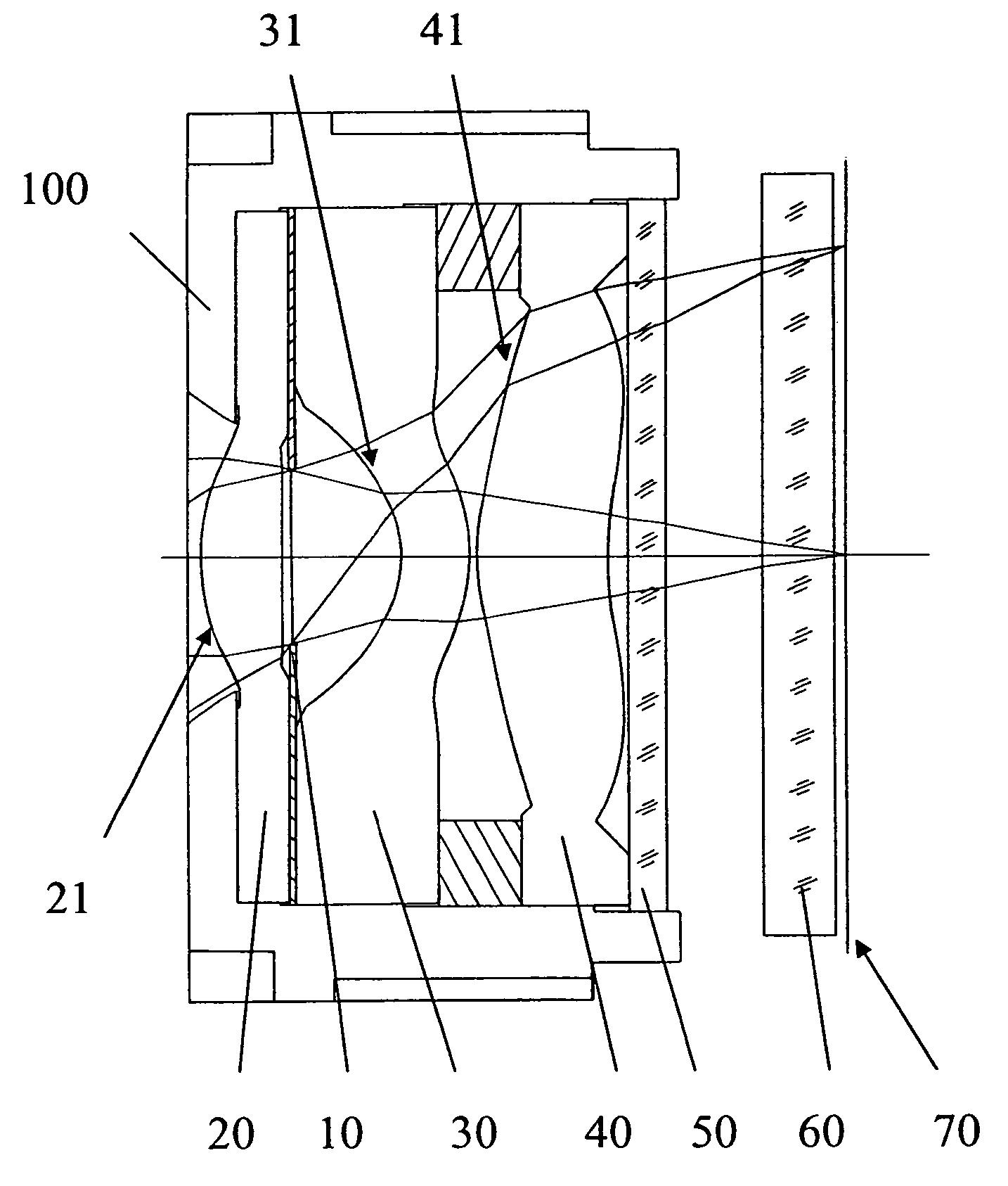
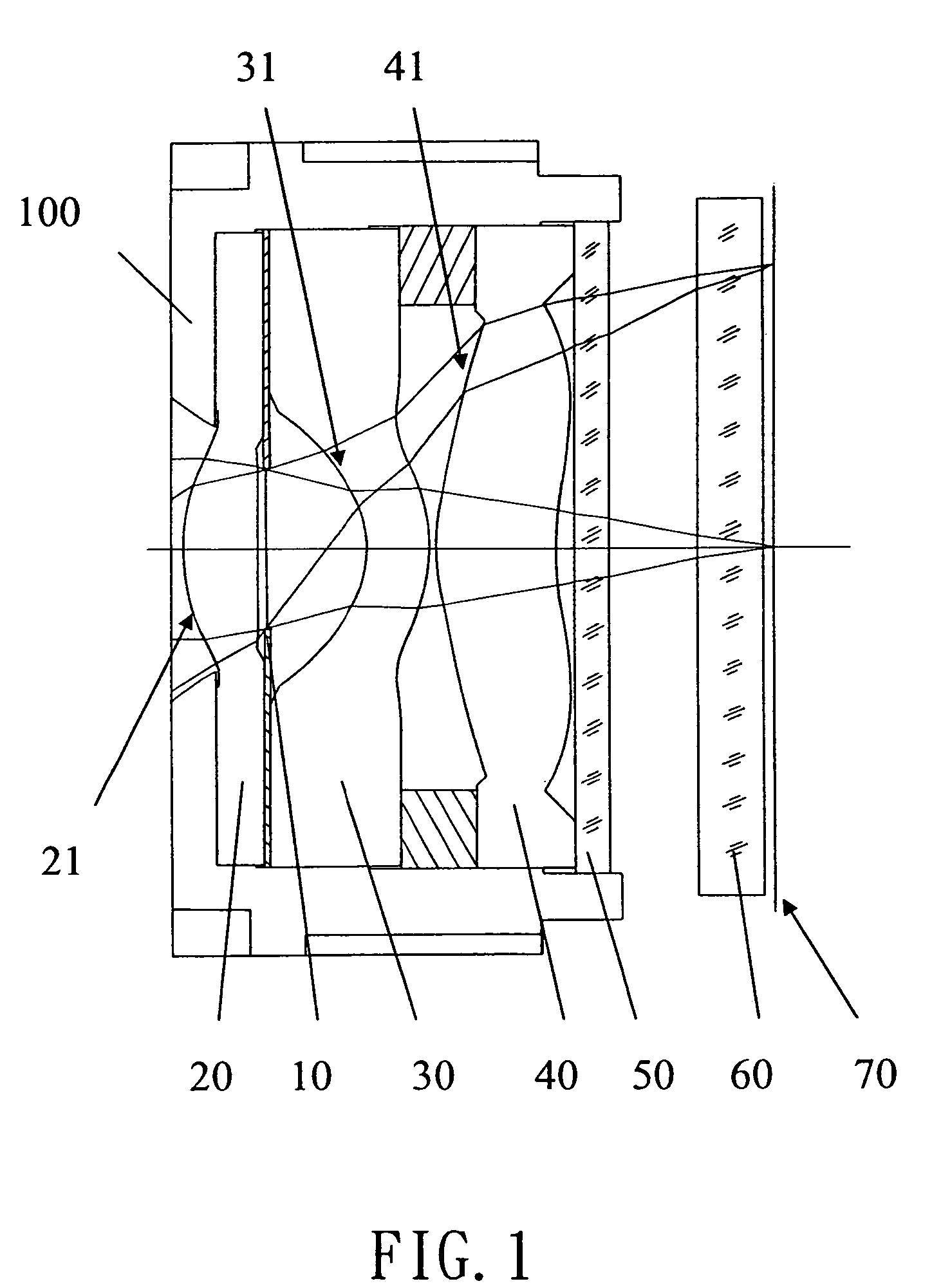
[0020]Referring to FIG. 1, an image lens array 100 in accordance with the present invention, from the object side, comprises a first lens 20, an aperture 10, a second lens 30, a third lens 40, an infrared filter 50, a sensor cover glass 60 and an image-forming plane 70.

[0021]The first lens 20 is a meniscus lens with positive refracting power and has a convex surface 21 facing forward so as to balance the astigmatic aberration and field curvature caused in the optical system.

[0022]The second lens 30 is a negative meniscus lens with a concave surface 31 facing forward.

[0023]The third lens 40 is a positive lens with a convex surface 41 facing forward.

[0024]The infrared filter 50 is a flat glass that does not affect the focal length of the optical system.

[0025]The sensor cover glass 60 is also a flat glass that does not affect the focal length of the optical system.

[0026]The first lens 20 is made of plastic material and its radius of curvature of front and back surfaces is L1R1 and L1R2...

second embodiment

[0031]Referring to FIG. 3, an image lens array 100 in accordance with the present invention, from the object side, comprises a first lens 20, an aperture 10, a second lens 30, a third lens 40, an infrared filter 50, a sensor cover glass 60 and an image-forming plane 70.

[0032]The first lens 20 is a meniscus lens with positive refracting power and has a convex surface 21 facing forward.

[0033]The second lens 30 is a negative meniscus lens with a concave surface 31 facing forward.

[0034]The third lens 40 is a positive lens with a convex surface 41 facing forward. The first, second and third lenses 20, 30, 40 are provided with aspherical surfaces.

[0035]The infrared filter 50 and the sensor cover glass 60 are a flat glass that does not affect the focal length of the optical system. The image-forming effect of the optical system is achieved by the first, second and third lenses 20, 30, and 40.

[0036]The optical data of the second embodiment image lens array is shown in table 2. The central t...


PUM


Abstract

An image lens array, from object side, comprises: a first positive meniscus plastic lens with a convex surface facing forward, a second negative meniscus plastic lens with a concave surface facing forward, a third positive meniscus plastic lens with a convex surface facing forward, and an infrared filter disposed in the lens barrel of the image lens array, the central thickness of the first and second lenses are: CT1<1.0 mm, CT2<0.6 mm. The radius of curvature of the front and back surfaces of the first lens are L1R1 and L1R2 that satisfy the condition as: |L1R1 / L1R2|<0.5. The radius of curvature of the front and back surfaces of the third lens are L3R1 and L3R2 that satisfy the condition: |L3R1 / L3R2|>0.3.

Description

BACKGROUND OF THE INVENTION[0001]1. Field of the Invention[0002]The present invention relates to an image lens array for a small image taking device, and particularly to a mid-aperture type image lens array consisted of three plastic lenses that are provided with aspherical surfaces.[0003]2. Description of the Prior Arts[0004]Since the image pick up lens has an increasingly wide range of application, plus the consumer electronic industrial is growing fast, the small image pick-up lens is accordingly found in great demand in different fields, particularly in photographic cell phone, digital camera, or auto's detection system for parking or other purposes.[0005]A photosensitive element for a digital fixed focus lens array generally includes charge coupled device (CCD) type or CMOS type Complementary Metal Oxide Semiconductor, and its light sensitivity will be reduced sharply with the increase of exit angle of the lens. Therefore, the digital fixed focus lens array is usually provided ...

Claims


Application Information

Patent Timeline
Patent Type & Authority Patents(United States)
IPC IPC(8): G02B9/00G02B13/04G02B3/02
CPCG02B13/0035
Inventor HUANG, YEO-CHIH
Owner LARGAN PRECISION
Why Eureka
Try Eureka