
System and method of timing and frequency control in TDM/TDMA networks

a technology of tdm/tdma network and timing and frequency control, which is applied in the direction of digital transmission, multiplex communication, selective content distribution, etc., can solve the problems of jitter in the received pcr value affecting the stability of tcxo, requiring expensive tcxo, and inaccurate frequency synchronization with the hub

Active Publication Date: 2007-08-28
VIASAT INC
View PDF3 Cites 18 Cited by
  • Summary
  • Abstract
  • Description
  • Claims
  • Application Information

AI Technical Summary

Benefits of technology

The present invention relates to a system and method for synchronizing network devices using a time division multiplexing (TDM) demodulator and a frequency synchronizer. The technical effects of this invention include a faster settling time (on the order of a few seconds) which allows for the use of a less expensive TCXO, and the use of recovered symbol timing and PCR timestamps in the TDM signal for improved synchronization accuracy. Additionally, the invention provides a more cost-effective and efficient solution for synchronizing network devices.

Problems solved by technology

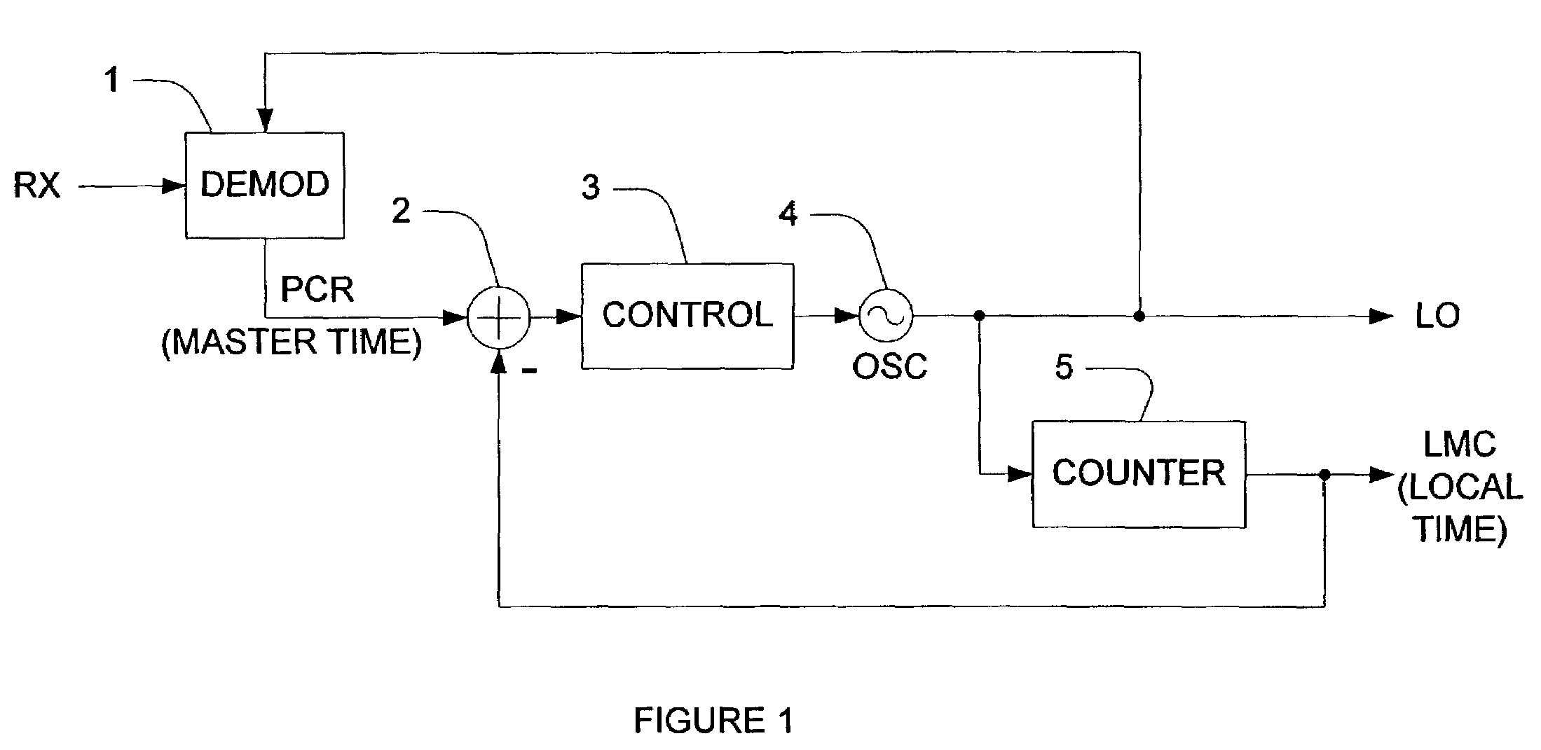
Second, the jitter in the received PCR values affects TCXO stability, since adjustments are made to the TCXO 4 periodically based on the PCR values.
Otherwise, the TCXO 4 will change its frequency during the time that it is being adjusted by the loop, and frequency synchronization with the hub will not be accurate.
To meet this requirement, an expensive TCXO is required.
Thus, there is a cost disadvantage to the TCXO of the related art system.
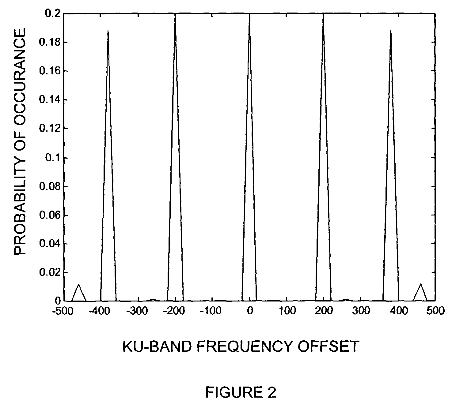
Although the average stability for the uniform and Gaussian jitters are substantially the same, Gaussian jitter can produce much higher errors than uniform jitter.
However, such a low bandwidth requires about 25 minutes for the transient error at Ku-band to decrease to about 30 Hz.
However, this related art hub must to tolerate a larger frequency error during startup.

Method used


Image

  • System and method of timing and frequency control in TDM/TDMA networks
  • System and method of timing and frequency control in TDM/TDMA networks
  • System and method of timing and frequency control in TDM/TDMA networks

Examples


Embodiment Construction

[0043]Reference will now be made in detail to the preferred embodiment of the present invention, examples of which are illustrated in the accompanying drawings. In the present invention, the terms are meant to have the definition provided in the specification, and are otherwise not limited by the specification.

[0044]The present invention includes a system and method for synchronizing two nodes of a network in time and frequency. An exemplary description of the present invention includes a hub as the first node and a terminal as the second node. However, the exemplary description is non-limiting, and other embodiments may also be included in the present invention. For example, but not by way of limitation, a peer to peer configuration, with at least two equal peers that communicate with one another, may be included in the present invention. Further, the present invention is also not limited to satellite, and other implementations may be provided as would be understood by one skilled ...


PUM


Abstract

A method and system of synchronizing two nodes of a network uses a demodulated output signal of a time division multiplex (TDM) demodulator to perform frequency and timing synchronization independently. Frequency synchronization is performed without using a program clock reference, by detecting a symbol timing loop error of the TDM demodulator. The error is filtered by an oscillator control loop filter if the error is within a predetermined range. Thus, an output voltage of a digital to analog converter that receives the filtered output controls an oscillator. In the timing synchronizer, an error between a program clock reference (PCR) and a value of a counter in the terminal is computed if the PCR is a not a first PCR, and the error is filtered with a timing loop control filter. A processor then adjusts a value of the counter in the terminal based on the filtered output.

Description

[0001]This application claims benefit to Provisional Application No. 60 / 352,870 filed Feb. 1, 2002; the disclosure of which is incorporated herein by reference.BACKGROUND OF THE INVENTION[0002]1. Field of the Invention[0003]The present invention relates to a method of synchronizing two nodes of a communications network in time and frequency. More specifically, frequency and time are synchronized independently to improve stability and reduce cost in a satellite communication system.[0004]2. Background of the Related Art[0005]In the related art, satellite networks with “star” connectivity are used in various applications. For example, a hub of the star network transmits an outbound continuous time signal. The outbound signal is usually Time Division Multiplexed (TDM), and contains packets for a particular terminal or alternatively, multicast data. Correspondingly, the return link from the terminals to the hub uses Time Division Multiple Access (TDMA). In the related art, standardizati...

Claims


Application Information

Patent Timeline
Patent Type & Authority Patents(United States)
IPC IPC(8): H04J3/06H04B7/212H04B7/26H04L7/02
CPCH04B7/2125H04L7/0054H04L27/0014H04N21/4305H04B7/2687H04H20/86H04H60/68H04L2027/0053
Inventor CRONIN, CHRISTOPHER J.BALASUBRAMANIAN, RAMAKRISHNAN
Owner VIASAT INC
Learn More