Supercharge Your Innovation With Domain-Expert AI Agents!

Mounting case for electro-optical device, method of manufacturing mounting case for electro-optical device, electro-optical device, and electronic apparatus

a technology for electro-optical devices and mounting cases, which is applied in the direction of non-linear optics, instruments, television systems, etc., can solve the problems of degradation of the shape of mounting cases is relatively complicated, and the manufacturing quality of mounting cases is affected, so as to achieve stable manufacturing quality and low cost

Inactive Publication Date: 2007-08-28
SEIKO EPSON CORP
View PDF10 Cites 12 Cited by
  • Summary
  • Abstract
  • Description
  • Claims
  • Application Information

AI Technical Summary

Benefits of technology

The invention provides a mounting case for an electro-optical device that can be manufactured with consistent quality at a low cost. The mounting case is made by a pressing process, which prevents burr or erosion that can occur during die-casting. The mounting case includes a main body and a blade that extends from the main body and helps to improve cooling efficiency and prevent hot spots in the electro-optical panel, which can degrade display quality. The mounting case can be easily manufactured with a pressing process and can include other components that are also made by a pressing process. Overall, the invention provides a more efficient and cost-effective way to manufacture mounting cases for electro-optical devices.

Problems solved by technology

Therefore, a mounting case has a relatively complicated shape.
In die-casting, however, there is a problem in that the degradation of the manufacturing quality of the mounting case occurs due to burrs or erosion.
However, when manufactured by die-casting, a mounting case can be molded to have a relatively complicated shape.
If the blade is attached to the main body, the structure becomes complicated.
Therefore, it is difficult to reliably form such a structure by a pressing process.
However, when the manufacturing of components becomes complicated, the components may be molded by die-casting or the like to be bonded to or engaged with the main body or the like.
However, when the structure becomes complicated, the components may be molded by die-casting or the like to be bonded to or engaged with the main body or the like.
However, when the structure is complicated, the components may be molded by die-casting or the like to be bonded to or engaged with the main body or the like.

Method used


Image

  • Mounting case for electro-optical device, method of manufacturing mounting case for electro-optical device, electro-optical device, and electronic apparatus
  • Mounting case for electro-optical device, method of manufacturing mounting case for electro-optical device, electro-optical device, and electronic apparatus
  • Mounting case for electro-optical device, method of manufacturing mounting case for electro-optical device, electro-optical device, and electronic apparatus

Examples


Embodiment Construction

[0089]Embodiments of the invention will be described with reference with the drawings.

1: Embodiment of Electronic Apparatus

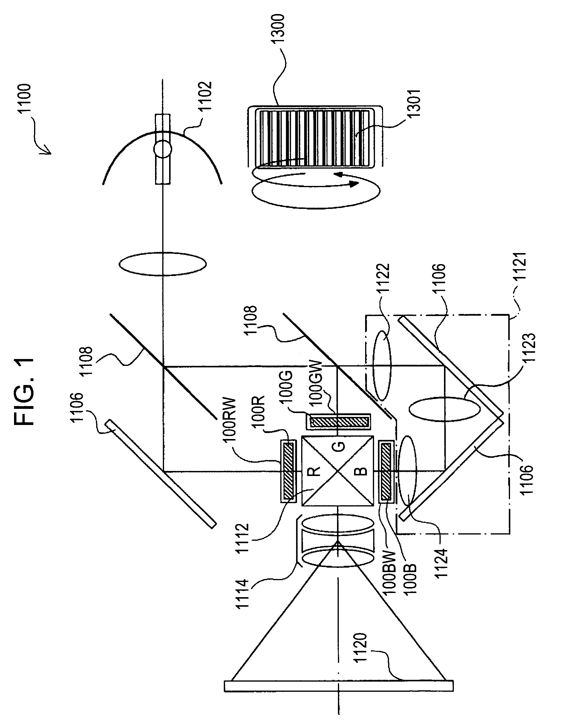
[0090]First, with reference to FIG. 1, a construction of an electronic apparatus of the present embodiment will be described. FIG. 1 shows a schematic construction of the electronic apparatus according to the present embodiment. Moreover, in the present embodiment, a projection-type liquid crystal projector will be taken as an example of the electronic apparatus according to the invention.

[0091]In FIG. 1, a liquid crystal projector 1100 is constructed with a multi-plate type color projector using three liquid crystal light valves 100R, 100G, and 100B for RGB.

[0092]In the liquid crystal projector 1100, the projection light emitted from a lamp unit 1102, which is a white light source, such as a metal halide lamp, is divided into R, G, and B light components corresponding to three primary colors including R, G, and B, by three mirrors 1106 and two dichroic mirrors ...


PUM

PropertyMeasurementUnit
timeaaaaaaaaaa
surface areaaaaaaaaaaa
shapeaaaaaaaaaa

Abstract

The inventions relate generally to a mounting case for an electro-optical device that includes a main body having a plate member formed by a pressing process, a bottom portion, and side portions continuous with the bottom portion to surround a side edge of the electro-optical panel so that the electro-optical panel may be accommodated therein. A heat-radiating blade corresponding to the circumferential edge of the main body of the plate member is partially formed by a pressing process and extends from the main body to the outside of the main body. A cooling air introducing portion extends from the circumferential edge in a direction toward the bottom portion for directing cooling air across the main body and over the heat-radiating blade for cooling the electro-optical panel. Detailed information on various example embodiments of the inventions are provided in the Detailed Description below, and the inventions are defined by the appended claims.

Description

BACKGROUND[0001]1. Technical Field[0002]The present invention relates to a mounting case, which is used for mounting an electro-optical panel such as a liquid crystal panel in an electro-optical device such as a liquid crystal device, to a method of manufacturing the same, to an electro-optical device including such a liquid crystal panel, and to an electronic apparatus such as a liquid crystal projector which uses the electro-optical device, for example, as a light valve.[0003]2. Related Art[0004]When this type of electro-optical panel is used as a light valve in an electronic apparatus such as a liquid crystal projector, the electro-optical panel is not installed into a case body, a casing, or a frame of the apparatus in an exposed state, but it is mounted or accommodated in a proper mounting case to be installed. The reason why an electro-optical panel is accommodated in a mounting case is that the fixing, the attaching, and the optical-positioning of the electro-optical panel wi...

Claims


Application Information

Patent Timeline
Patent Type & Authority Patents(United States)
IPC IPC(8): G02B6/00G02F1/1333G03B21/14G03B21/18
CPCG02F1/133308H04N9/3141H04N9/3144H04N9/3197G02F1/133385G02F2201/36H04N5/7441G02F1/1333
Inventor MIYASHITA, TOMOAKI
Owner SEIKO EPSON CORP
Features
  • R&D
  • Intellectual Property
  • Life Sciences
  • Materials
  • Tech Scout
  • Unparalleled Data Quality
  • Higher Quality Content
  • 60% Fewer Hallucinations
Learn More