

Torque-detecting device
a technology of torque detection and torque, which is applied in the direction of force sensors, instruments, volume meters, etc., can solve the problems of difficult to achieve accurate torque detection, reduced mechanical processability, and difficult to apply this alloy as a structural componen
- Summary
- Abstract
- Description
- Claims
- Application Information
AI Technical Summary
Benefits of technology
Problems solved by technology
Method used
Image

Examples
first embodiment
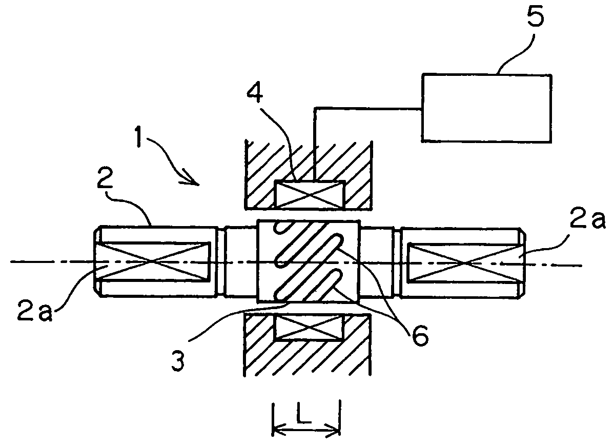
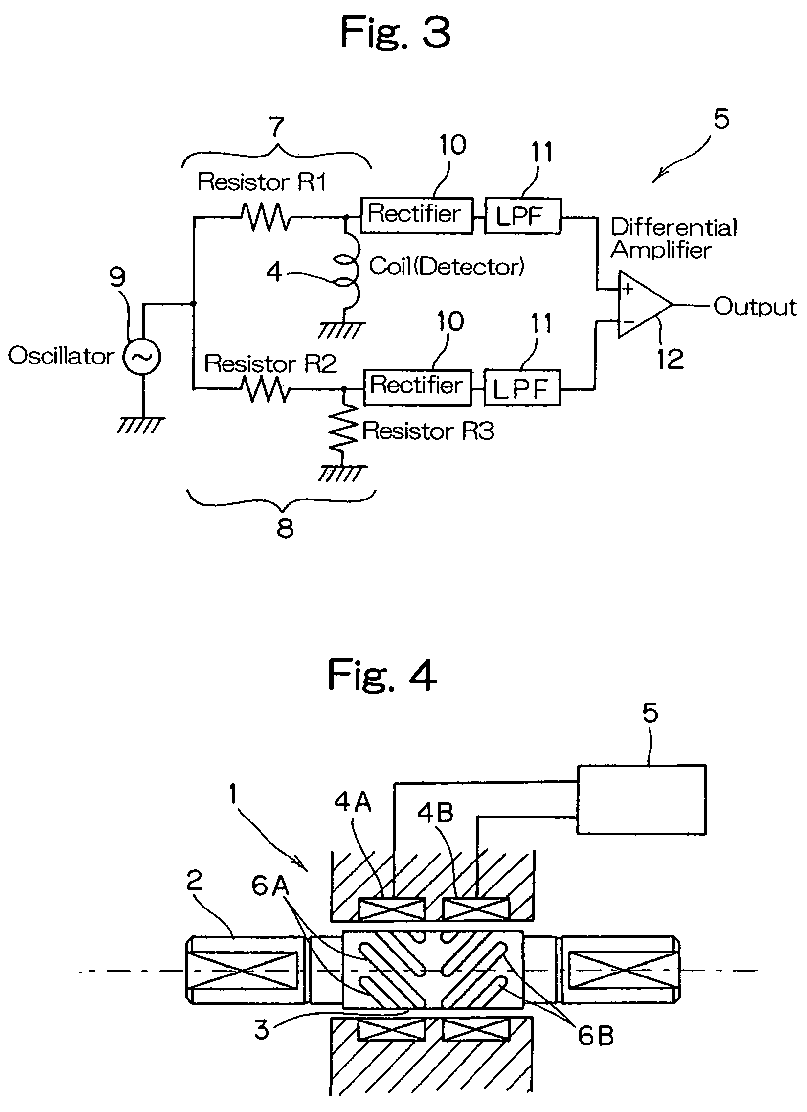
[0094]FIGS. 4 and 5 illustrate a third preferred embodiment of the present invention. The torque detecting device shown therein is substantially similar to that described with reference to FIG. 1, except that in this embodiment, the plural grooves 6 angled relative to the longitudinal axis of the torque transmitting shaft 2 are formed in two rows 6A and 6B in the target area subject to torque detection 3 while equidistantly spaced from each other in a circumferential direction of the latter, with the row of the grooves 6A inclined in a sense opposite to the row of the grooves 6B relative to the longitudinal axis of the torque transmitting shaft 2. In correspondence with the use of the two rows of the inclined grooves 6A and 6B, two detecting coils 4A and 4B are employed.
[0095]The detection signal processing means 5 utilizable in the practice of the third embodiment includes, as best shown in FIG. 5, a first series connected circuit 7A made up of a resistor R1 and the detecting coil...
third embodiment
[0096]In the torque detecting device 1 when the torque acts on the torque transmitting shaft 2 with a tensile stress acting on the first row of the grooves 6A of the target area subject to torque detection 3, a compressive stress acts on the second row of the grooves 6B. Accordingly, when the difference between detected values (changes in impedance) of the detecting coils 4A and 4B associated with the first and second rows of the grooves 6A and 6B is outputted as a detection signal, the direction and magnitude of a torsional torque acting on the torque transmitting shaft 2 can be determined in reference to the polarity (positive or negative) and magnitude of such output.
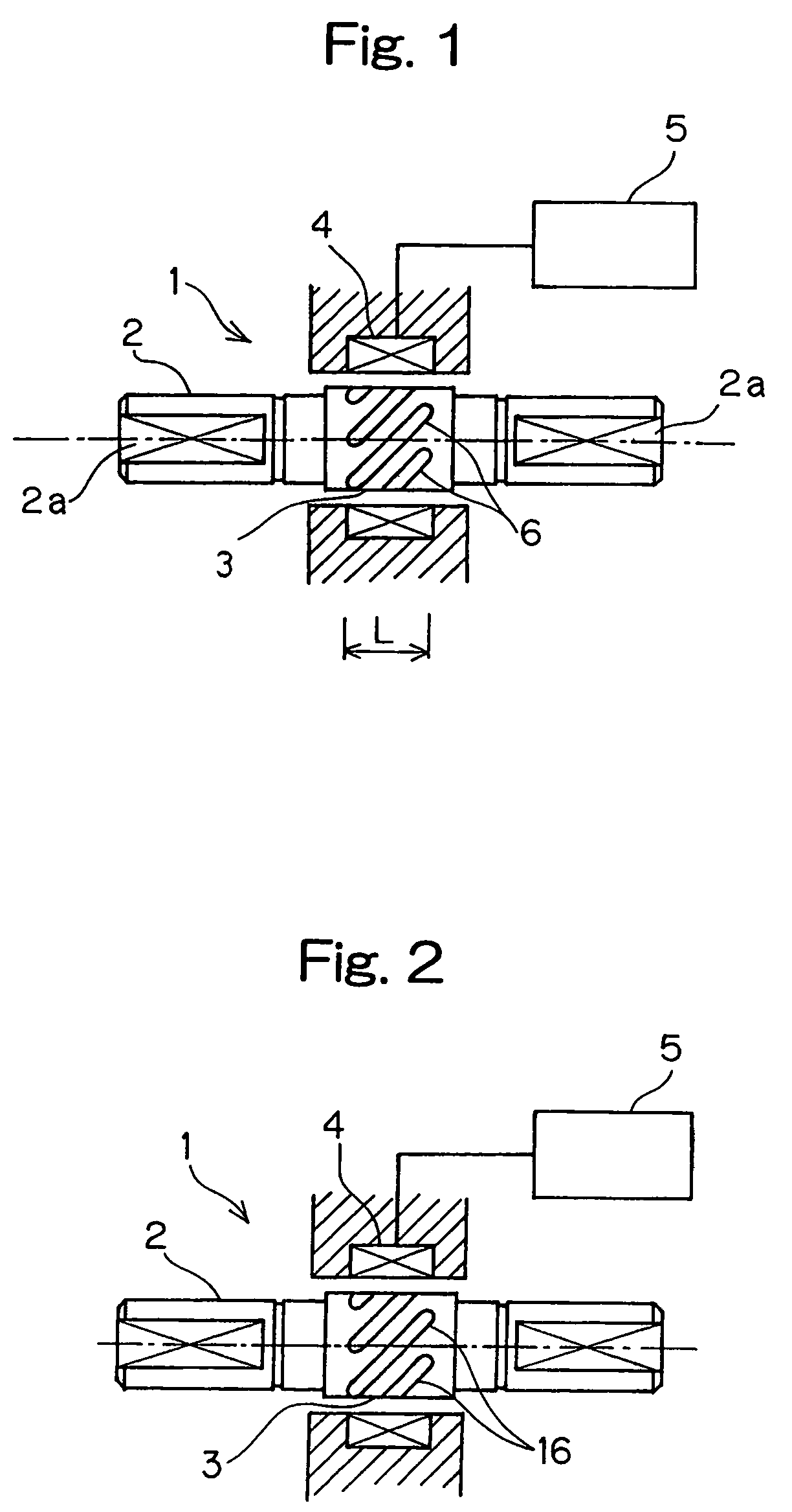
[0097]It is to be noted that in the third embodiment, in place of the first and second rows of the grooves 6A and 6B, two rows of diffusion layer formed islands 16 inclined relative to the longitudinal axis of the torque transmitting shaft 2, with one row of the diffusion layer formed islands being inclined in a sen...
second embodiment
[0100]The grooves 6 of the target area subject to torque detection 3 may, however, be replaced with the diffusion layer formed islands 16 such as shown and described in connection with the second embodiment with reference to FIG. 2.
[0101]It is to be noted that the inner race 20 of the rolling bearing 15 may be dispensed with and, instead, an outer periphery of the torque transmitting shaft 2 may be concurrently utilized as an inner race such as shown in FIG. 7 in connection with a fifth preferred embodiment of the present invention that follows.
[0102]FIG. 8 illustrates a sixth preferred embodiment of the present invention. The torque detecting device 1 according to this embodiment is such that the torque transmitting shaft 2 shown and described in connection with the first embodiment is applied in an inner race 20A of a rolling bearing 15A used to rotatably support a rotary shaft 23 of the motor 13. FIG. 8A is a sectional view of the rolling bearing 15A and FIG. 8B is a sectional vi...
PUM
| Property | Measurement | Unit |
|---|---|---|
| thickness | aaaaa | aaaaa |
| depth of diffusion | aaaaa | aaaaa |
| skin depth | aaaaa | aaaaa |
Abstract
Description
Claims
Application Information