Control apparatus of internal combustion engine

a control apparatus and internal combustion engine technology, applied in the direction of electric generator control, machines/engines, propulsion parts, etc., can solve the problems of large accumulated difference, large variation in the number of engine revolutions after executing the fuel cut until the actual stopping of the engine, and it is practically difficult to control the engine stop position in a constant manner. , to achieve the effect of accurate stopping and small energy consumption

Active Publication Date: 2007-09-04
TOYOTA JIDOSHA KK
View PDF25 Cites 36 Cited by
  • Summary
  • Abstract
  • Description
  • Claims
  • Application Information

AI Technical Summary

Benefits of technology

[0013]The present invention is contrived in view of the above-described problems, and its object is to provide a control apparatus of an internal combustion engine capable of accurately stopping the engine at a predetermined stop position with small energy. Another object of the present invention is to provide a control apparatus of an internal combustion engine for realizing early ignition start of the internal combustion engine.

Problems solved by technology

However, in the method for executing the fuel cut at the predetermined crank angle for the specific cylinder in order to stop the engine at the predetermined position, since the states of engine loads of auxiliary machines and the like at the time of executing the fuel cut and the number of engine revolution immediately before the fuel cut are not always constant, the falling manner of the number of the engine revolution after executing the fuel cut until actual stopping of the engine may vary.
No matter how small it may be, such a variation finally brings about a large accumulated difference.
Consequently, it is practically difficult that the engine stop position is always controlled in a constant manner.
In the method for controlling the engine stop position by utilizing the balance with the compression torque at the time of stopping the engine, first, it is difficult to accurately predict the value of the compression torque.
Further, a large motor is needed because a large torque has to be produced in order to balance with the compression torque, and hence the power consumption becomes large.
However, as the motor for starting is miniaturized, the possible output torque becomes small.
As a result, there occurs a problem that the time until the completion of the first explosion of the engine becomes long.
Also, when the motor for starting is miniaturized, falling of the torque when the number of engine revolution increases becomes large.
Therefore, even if a piston of the cylinder in the compression stroke can get over the first compression stroke top dead center by the motoring by the starter motor, the piston may not get over the next compression stroke top dead center because enough inertia energy of the engine cannot be generated due to the decreasing outputting torque of the starter motor when the number of engine revolution increases.
In the worst case, the motor may lock around the top dead center.
Further, there may also occur a problem that the time until the completion of the first explosion becomes long because it takes considerable time to determine the cylinder when the number of engine revolution is low.

Method used


Image

  • Control apparatus of internal combustion engine
  • Control apparatus of internal combustion engine
  • Control apparatus of internal combustion engine

Examples


1st embodiment

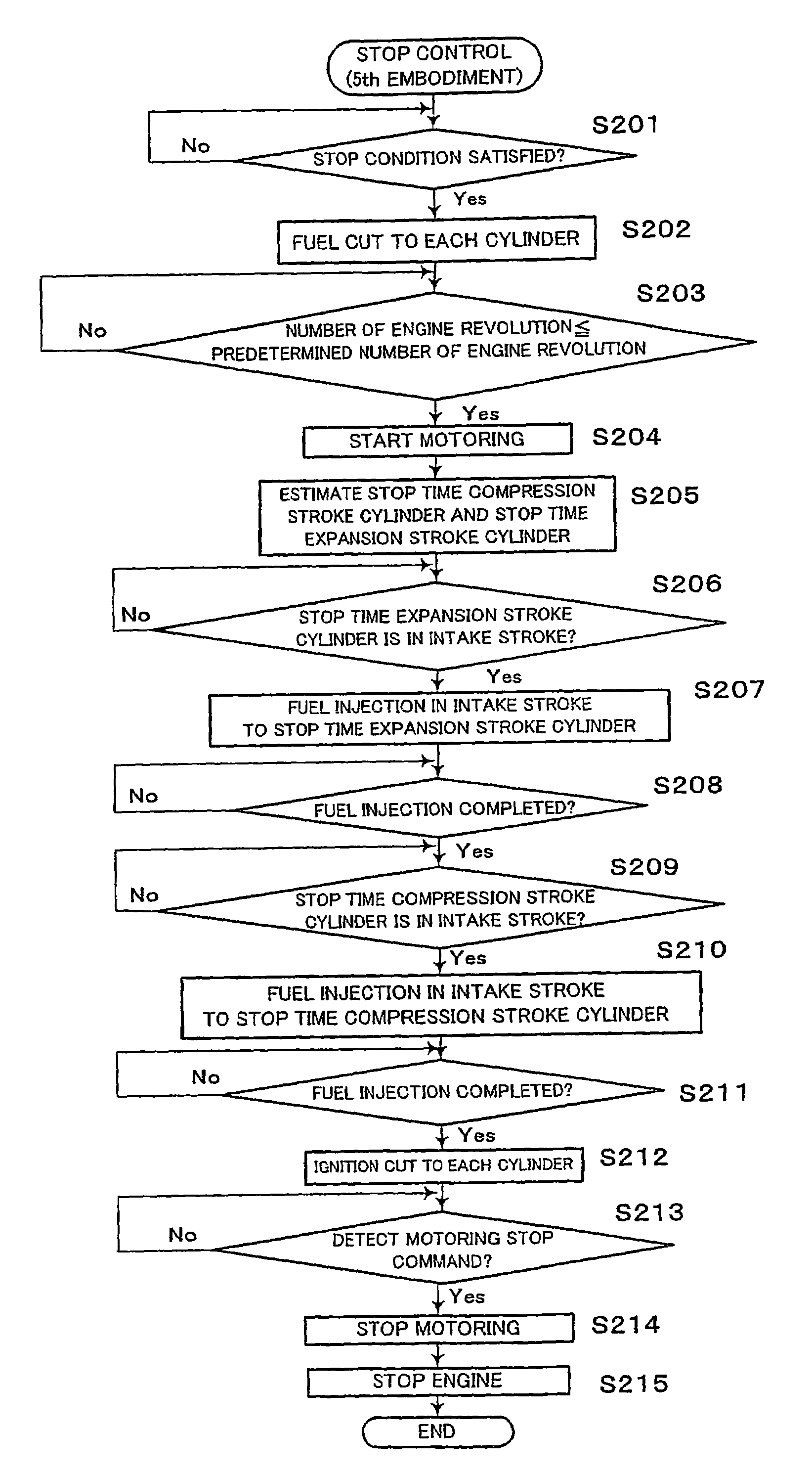
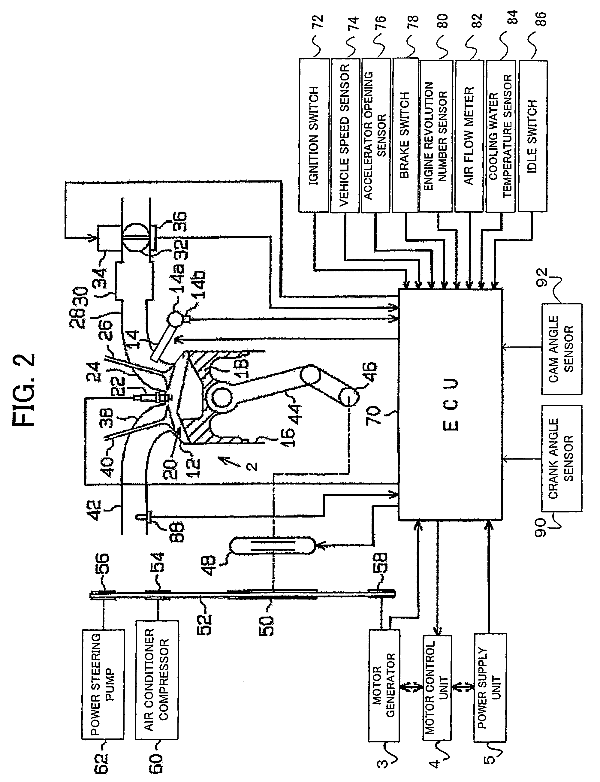
[0109]A method for controlling the crank angle to the optimal crank angle stop position will be described hereinafter. The optimal crank angle stop position is assumed to be a stop position of the crank angle, which makes it easy to get over the top dead center of the compression stroke at the time of restarting the engine 2 in the cylinder at the compression stroke. For example, in the case of the four-cylinder engine as in this example, the crank angle stop position is optimal if it is within a range of the crank angle of 90° CA to 120° CA.

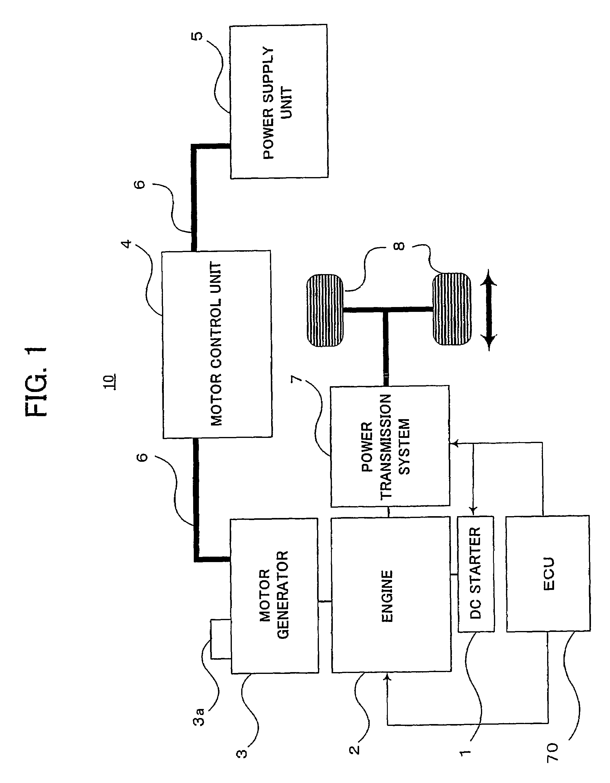
[0110]In summary, in the ordinary stop control method of the vehicle 10, the ECU 70 executes fuel cut to the engine 2 at a predetermined timing from the idling state, and automatically stops the engine 2 by the inertia energy which the engine 2 has thereafter. However, the inertia energy which the engine 2 has varies each time according to the number of engine revolution at the time of the fuel cut, and the crank angle stop position differs each...

1st application example

[0134]Next, the description will be given of an application example of the engine stop control according to this embodiment. In this embodiment, when the number of engine revolution NE reaches the motor setting number of revolution NE2, the motoring is executed for the predetermined time, so that the number of engine revolution NE becomes the predetermined motor setting number of revolution NE2 when the motoring is stopped. However, the output of the motor generator 3 may lower because of deterioration of the power supply unit (battery), and the number of engine revolution at the time of stopping the motoring may be lower than the motor setting number of revolution NE2. When the number of engine revolution is lower than the motor setting number of revolution NE2, the engine cannot be stopped at the optimal crank angle stop position because the scheduled inertia energy cannot be by driving the motor generator 3, even after the usual motoring stopping timing. Thereby, it is possible t...

2nd application example

[0138]The second application example relates to a processing when engine start is requested during the engine stop control according to the above-described first embodiment. It is noted that the engine restart is requested during the idling stop, for example, when the driver releases the brake, or when the predetermined time elapses from the brake off operation, or when the accelerator is ON, or the like.

[0139]First, with reference to a flow chart in FIG. 7, when the engine start is requested during the fuel cut (step S3) in the engine stop control, the ECU 70 may cancel the fuel cut and restart the fuel injection. In this case, if the number of engine revolution is lower than the predetermined number of engine revolution, it is preferred that the assist of the driving force is executed by the motor generator 3 to improve the starting performance.

[0140]Next, when the engine start is requested during the motoring (step S5) in the engine stop control, the ECU 70 may restart the fuel i...


PUM


Abstract

At a time of stopping an internal combustion engine, inertia energy of the engine is kept constant, for example, by controlling a number of engine revolution constant, while controlling combustion of the engine. By utilizing the controlled inertia energy, the engine is stopped at a predetermined crank angle position. Since the engine is stopped at the predetermined crank angle position by utilizing the controlled inertia energy, a large amount of energy for controlling the stop position of the energy is not needed, and the energy needed for the stop control can be reduced. Since the inertia energy utilized for the stop control is always controlled in a predetermined state, the engine can be stopped at a proper position reliably each time.

Description

TECHNICAL FIELD[0001]The present invention relates to a control apparatus of an internal combustion engine. Particularly, the present invention relates to a stop and start control for stopping the internal combustion engine at a position at which energy needed at the time of starting is the smallest, and at the same time, for executing early start of the engine by igniting fuel introduced and sealed in a specific cylinder at the time of starting.BACKGROUND ART[0002]Recently, there is known an engine stop and start control apparatus for automatically stopping an internal combustion engine (hereinafter, also referred to as “engine”) when the vehicle stops and for automatically restarting the engine to start the vehicle when an instruction to start is given in the stopped state, in order to reduce a fuel consumption amount and exhaust gas during idling, from the viewpoint of environmental conservation, resources and energy saving or the like. This control is also called “idling stop” o...

Claims


Application Information

Patent Timeline
Patent Type & Authority Patents(United States)
IPC IPC(8): F02N11/04F02D29/06B60K6/485B60K6/547B60W10/06B60W10/08B60W20/00F02D31/00F02D41/04F02D41/12F02D41/36F02N11/08
CPCB60K6/485B60K6/547B60W10/06B60W10/08B60W20/00F02D31/008F02D41/0087F02D41/042F02D41/126F02N11/04F02N11/0818B60W2510/0628B60W2710/0616B60W2710/0644B60W2710/065F02D31/009F02D41/1454F02D41/187F02D2200/0404F02D2200/501F02D2200/602F02N11/0814F02N15/003F02N19/005F02N2019/008F02N2200/022Y02T10/6226Y02T10/6286Y02T10/48B60K2006/268Y02T10/40Y02T10/62F02D41/34F02N11/08B60W20/15
Inventor KATAOKA, KENJIKUSAKA, YASUSHITASAKI, HIROKI
Owner TOYOTA JIDOSHA KK
Why Eureka
Try Eureka