Method and device for pressure controlled sequential operation

a sequential operation and pressure control technology, applied in the direction of fluid removal, servomotor components, borehole/well accessories, etc., can solve the problems of reducing the applicability of the valve, electrical conductors are often exposed to damage, and working fluid is unsuitable for the use of the valve of this type, so as to achieve the effect of greatly improving the reliability of the valv

Active Publication Date: 2007-09-04
WEATHERFORD NORGE
View PDF15 Cites 28 Cited by
  • Summary
  • Abstract
  • Description
  • Claims
  • Application Information

AI Technical Summary

Benefits of technology

[0019]Thus the working fluid pressure acting on the dividing piston is controlled by the flow rate of the working fluid. The sequence of the control system may thereby be controlled by regulating the volume rate of working fluid being pumped to the downhole tool at all times.
[0020]The method of the invention allows the hydraulic control system to work with a clean hydraulic fluid that may have a higher maximum pressure than the working fluid, whereby the functional reliability is greatly improved, especially during operations that call for multiple sequences.

Problems solved by technology

These forms of communication have shortcomings that to a considerable extent reduce their applicability, as telemetry requires the use of relatively sensitive instrumentation, and the use of rotational frequencies is dependent on the downhole tool being rotatable.
Electrical conductors are often exposed to damage.
For complex operations that require the use of a large number of relatively sensitive valves, and where the pressure interval between the opening of one valve in the sequence and the opening of the next is small, it has been found that, due to a reduced operational safety in the valve system, working fluid is unsuited for use in valves of this type.
A further adverse effect of pressure controlled sequential operation is that the remaining tool functions, where use is made of e.g. hydraulic cylinders, are often influenced by pressure variations in the working fluid.
Moreover, it has been found that the maximum pressure of the working fluid is often too low to allow the execution of certain operations connected with a downhole tool.

Method used


Image

  • Method and device for pressure controlled sequential operation
  • Method and device for pressure controlled sequential operation

Examples


Embodiment Construction

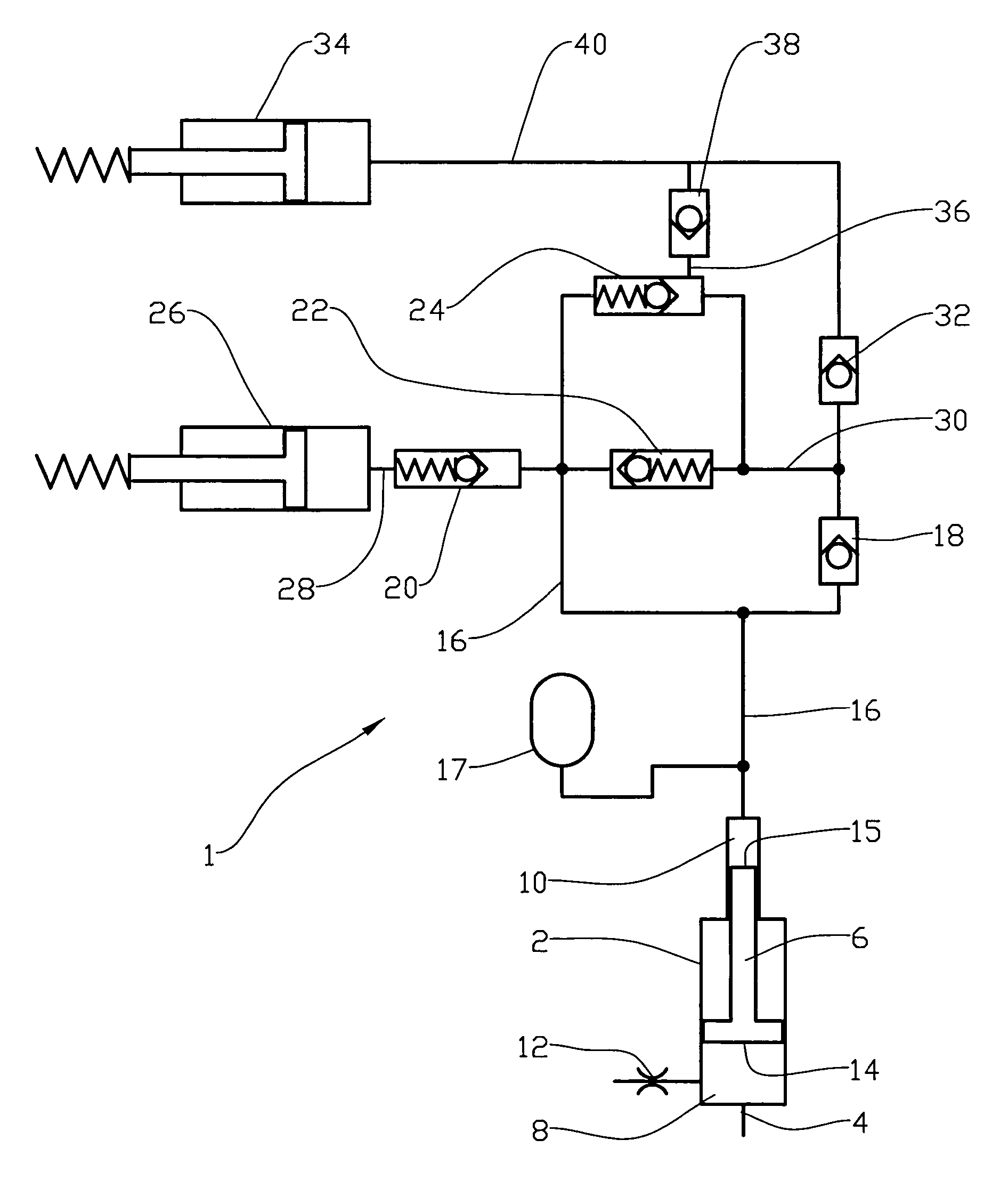
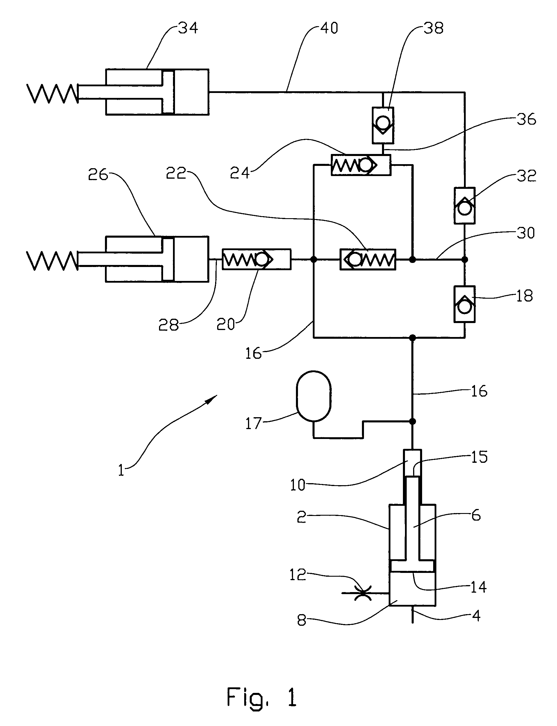
[0023]In FIG. 1, reference number 1 denotes a hydraulic sequential control system for a downhole tool (not shown).

[0024]Working fluid may flow from e.g. coiled tubing (not shown) and through an inlet port 4 into a booster 2. A piston 6 in the booster 2 sealingly separates a working fluid chamber 8 and hydraulic fluid chamber 10 of the booster 2.

[0025]A throttle valve 12 communicates with the working fluid chamber 8 and is arranged to throttle an outlet from the working fluid chamber 8.

[0026]Preferably the piston 6 is designed so that the working fluid acts on a piston area 14, which is larger than a piston area 15 acting on the hydraulic fluid.

[0027]From the hydraulic fluid chamber 10, hydraulic fluid flows via a first distribution line 16 to an accumulator 17, the closing port of a first check valve 18, a first pressure relief valve 20, a second pressure relief valve 22 and the inlet port of a controlled pilot valve 24. The first pressure relief valve 20, which is arranged to open ...


PUM


Abstract

A method and a device for controlling a downhole hydraulic sequential control system (1) in which a number of pressure relief valves (20, 22) are arranged to open sequentially directly or indirectly for corresponding actuators (26, 34) through introduction of a hydraulic fluid, wherein the pressure of working fluid supplied to the control system is transmitted to hydraulic fluid in the control system (1). The pressure transfer may be effected by means of a dividing piston (6).

Description

CROSS-REFERENCE TO RELATED APPLICATIONS[0001]This application claims benefit of Norwegian provisional patent application number 2002 6182, filed Dec. 23, 2002, which is herein incorporated by reference.BACKGROUND OF THE INVENTION[0002]1. Field of the Invention[0003]This invention regards a method of pressure controlled sequential operation. More particularly, it concerns a method of controlling a sequence of operations in a downhole tool. The invention also comprises a device for implementing the method.[0004]2. Description of the Related Art[0005]When working under ground, e.g. in a borehole, it is vital that the order of a sequence of individual operations may be controlled in a reliable manner.[0006]It is known to use telemetry and rotational frequencies to communicate from the surface and down to the downhole tool in, for example, a pipe string. The use of electrical signals for such communication is also known.[0007]These forms of communication have shortcomings that to a consi...

Claims


Application Information

Patent Timeline
Patent Type & Authority Patents(United States)
IPC IPC(8): E21B34/06E21B23/04E21B34/10
CPCE21B23/04E21B34/10
Inventor AKSELBERG, FRANK
Owner WEATHERFORD NORGE
Why Eureka
Try Eureka