Eureka AIR delivers breakthrough ideas for toughest innovation challenges, trusted by R&D personnel around the world.

Hydraulic passage structure of automatic transmission friction element

Inactive Publication Date: 2007-09-04
JATCO LTD
View PDF9 Cites 2 Cited by
  • Summary
  • Abstract
  • Description
  • Claims
  • Application Information

AI Technical Summary

Benefits of technology

[0006]Processing to form grooves g, h, and i and drum hole k involves bringing machining tools into proximity of the outer circumference of center boss portion f from a radial direction to carry out the processing. However, a transmission case a exists radially outward from center boss portion f, and makes such processing impossible or difficult. For this reason, midway wall b is formed as a separate part from transmission case a and is installed in transmission case a after processing of center boss portion f of midway wall b. This results in cost disadvantages including increased man-hours required for assembly.
[0009]It is therefore an object of the present invention to provide a hydraulic passage structure of an automatic transmission friction element, which is capable of requiring fewer man-hours and therefore lower cost to assemble.
[0010]It is another object of the present invention to provide a hydraulic passage structure of an automatic transmission friction element, which is capable of having a smaller clutch drum inner diameter and therefore a smaller clutch piston inner diameter to avoid the problem of the transmission becoming large in the radial direction.

Problems solved by technology

However, in order to support clutch drum d to be freely rotatable on center boss portion f of midway wall b according to the related art, restrictions arise in the processing necessary to form the clutch fluid passage which includes groove g, the fitting grooves of seal rings h and i, and drum hole k.
However, a transmission case a exists radially outward from center boss portion f, and makes such processing impossible or difficult.
For this reason, midway wall b is formed as a separate part from transmission case a and is installed in transmission case a after processing of center boss portion f of midway wall b. This results in cost disadvantages including increased man-hours required for assembly.
This means that an automatic transmission which houses such an assembly must take on an undesirably large size in the radial direction.
Seal ring grooves holding seal rings h and i become worn when seal rings h and i rotate upon being pulled by clutch drum d which revolves relative to center boss portion f. There is therefore difficulty in maintaining seal effectiveness.

Method used


Image

  • Hydraulic passage structure of automatic transmission friction element
  • Hydraulic passage structure of automatic transmission friction element
  • Hydraulic passage structure of automatic transmission friction element

Examples


Embodiment Construction

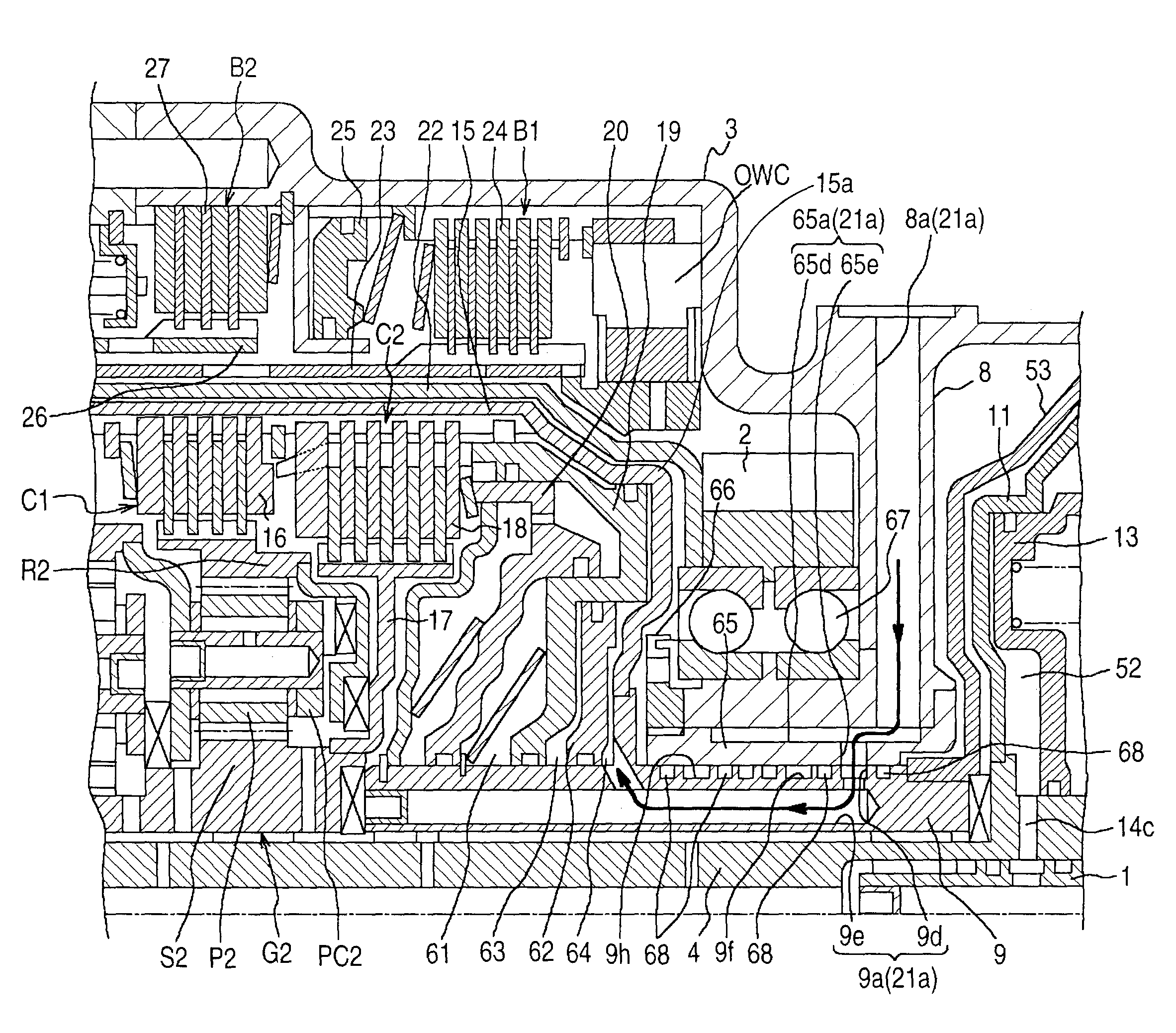
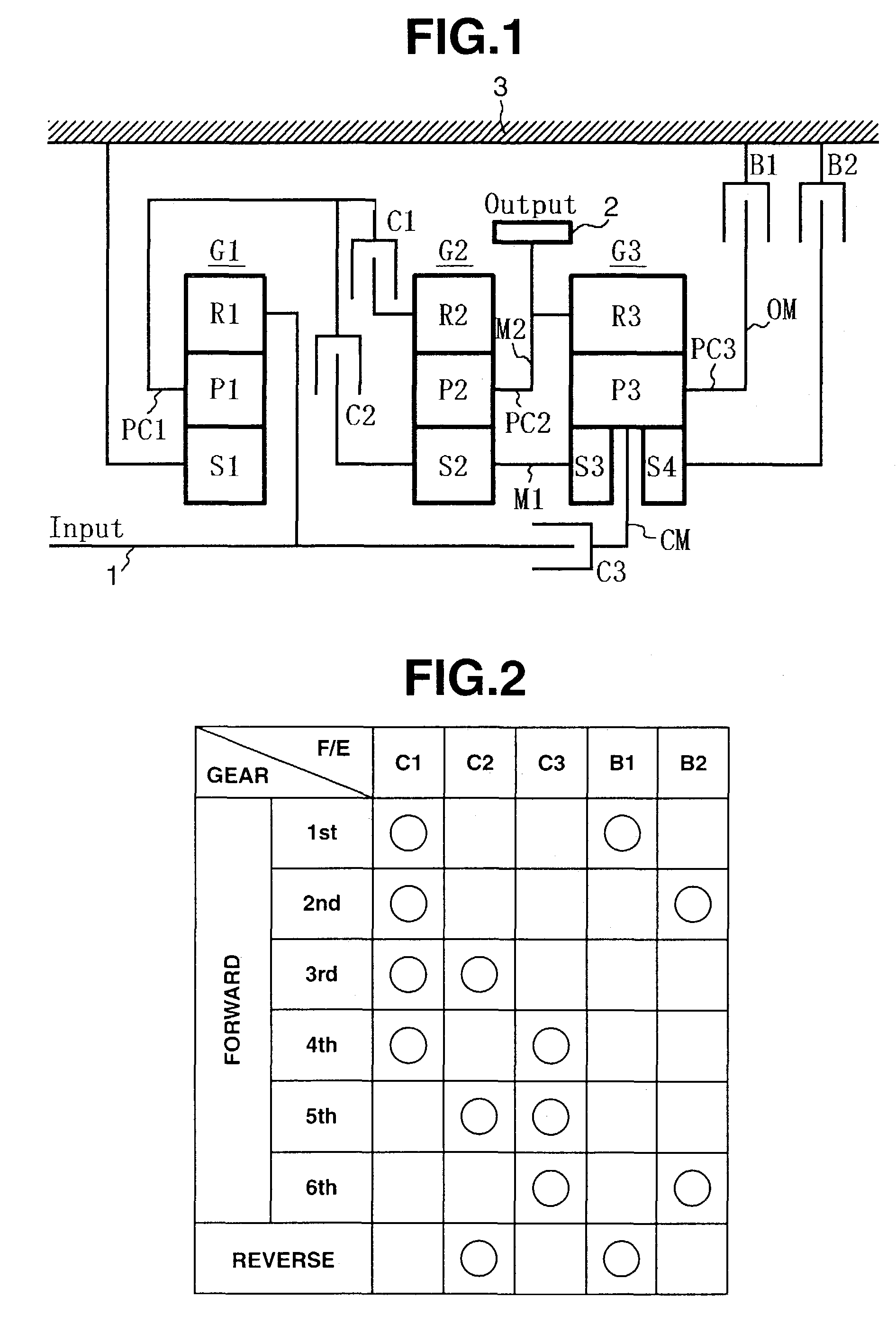
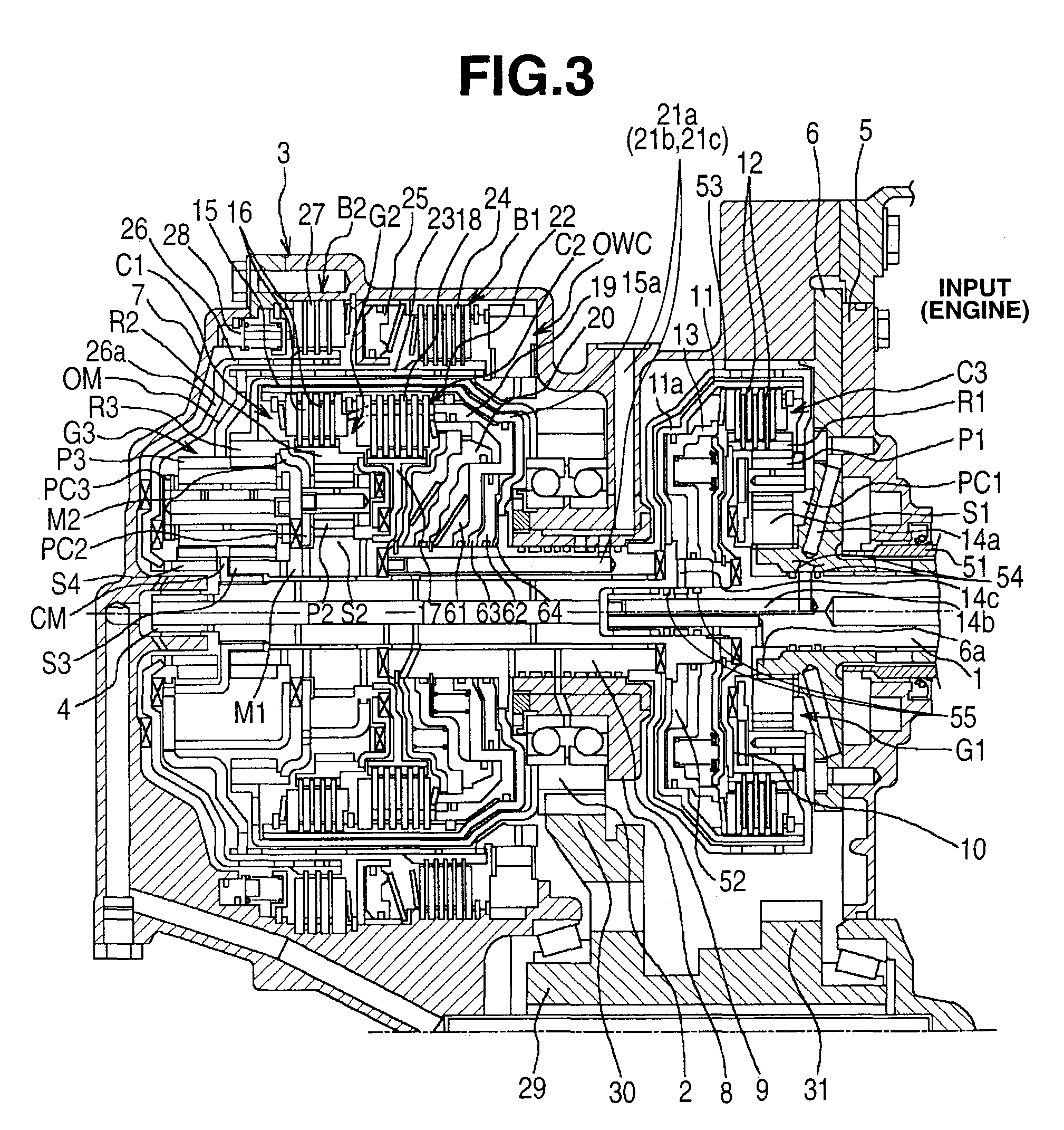
[0021]Referring to the drawings, there is discussed an embodiment of a hydraulic passage structure of an automatic transmission friction element in accordance with the present invention.

[0022]Referring to FIG. 1, an automatic transmission comprises a first planetary gearset G1, a second planetary gearset G2, a third planetary gearset G3, a first connecting member M1, a second connecting member M2, a first clutch C1, a second clutch C2, a third clutch C3, a first brake B1, a second brake B2, an input member Input which is an input shaft, and an output member Output which is an output gear 2.

[0023]A gearshift assembly for an automatic transmission according to the present invention comprises, in order starting from the left side of FIG. 1 which is the side closest to input member Input, first planetary gearset G1 as a reduction apparatus comprising a single-pinion planetary gearset which has a single set of planet-pinions, second planetary gearset G2 which is single-pinion, and third ...


PUM


Abstract

A hydraulic passage structure of an automatic transmission having at least one friction element for gearshift, the friction element being comprised of a drum. The hydraulic passage structure includes a housing formed integrally with a midway wall protruding inwardly from the housing, a sleeve, a center member joined integrally with the drum of the friction element, a radial passage in the midway wall, a sleeve passage in the sleeve, and a center member passage in the center member. The sleeve is fitted into an inner circumference of the housing, and the center member is inserted in an inner circumference of the sleeve. The sleeve passage connects with the radial passage of the housing, and the center member connects the sleeve passage and the friction element. Line pressure is supplied to the friction element via and in order of the radial passage, the sleeve passage, and the center member passage.

Description

[0001]The present invention relates to a hydraulic passage structure for friction elements which are responsible for gearshift control of an automatic transmission. In particular, it relates to a hydraulic passage structure for supplying fluid line-pressure via radial fluid passages in a midway wall to friction elements disposed adjacent to the midway wall, the midway wall being disposed within a transmission case perpendicularly to the axis of the transmission.BACKGROUND OF THE INVENTION[0002]The recent trend is to make automatic transmissions which are more stepped or graduated to provide slightly more forward gear ratios that can be selected so that shifting does not occur in too large steps, and therefore provide a smoother gearshift, as a way to realize improved fuel-efficiency and drivability. In order to realize this graduation of selectable gear ratios, gearshift assemblies have been designed for automatic transmissions which are formed by combining a reduction planetary gea...

Claims


Application Information

Patent Timeline
IPC IPC(8): F16D21/00F16H3/66F16H57/02F16H57/04F16H61/00
CPCF16H3/663F16H61/00F16H2200/0052F16H2200/201F16H2200/2023F16H2200/2097F16H2061/0046
Inventor IKEDA, YOICHI
Owner JATCO LTD
Why Eureka
Eureka Blog
Learn More