
Vehicle cockpit attachment structure with integrated plastic composite functional molded features

a functional molded, cockpit technology, applied in the direction of roofs, transportation and packaging, vehicle arrangements, etc., can solve the problems of physical and mechanical limitations of current cockpit structures, conflicting requirements of cockpit assemblies, etc., to improve the manufacture of cockpit assemblies, increase rigidity, and improve the effect of tensile strength

Inactive Publication Date: 2007-09-04
VISTEON GLOBAL TECH INC
View PDF26 Cites 17 Cited by
  • Summary
  • Abstract
  • Description
  • Claims
  • Application Information

AI Technical Summary

Benefits of technology

The present invention provides a cockpit assembly for a motor vehicle that overcomes limitations in previous designs. The assembly includes a cast alloy backbone, an intermediate plastic support member, and an instrument panel. The cast alloy backbone has attachment buttons that are integrally formed with the backbone, and the intermediate support member is separately molded to provide structural support for various devices in the assembly. The intermediate support member is made of a stronger plastic material than the instrument panel, which provides better tactile feel and more rigidity. The plastic material is molded through the attachment buttons and the interior space of the backbone. The attachment buttons are aligned side-by-side and in close proximity to each other, and the pairs of apertures are aligned along a lateral axis of the backbone. The technical effects of this design include improved manufacturing efficiency, better structural support, and improved tactile feel for the passenger.

Problems solved by technology

Thus, these cockpit assemblies are subjected to often conflicting requirements.
Current cockpit structures are physically and mechanically limited such that they meet only a certain subset of the expected requirements successfully.

Method used


Image

  • Vehicle cockpit attachment structure with integrated plastic composite functional molded features
  • Vehicle cockpit attachment structure with integrated plastic composite functional molded features
  • Vehicle cockpit attachment structure with integrated plastic composite functional molded features

Examples


Embodiment Construction

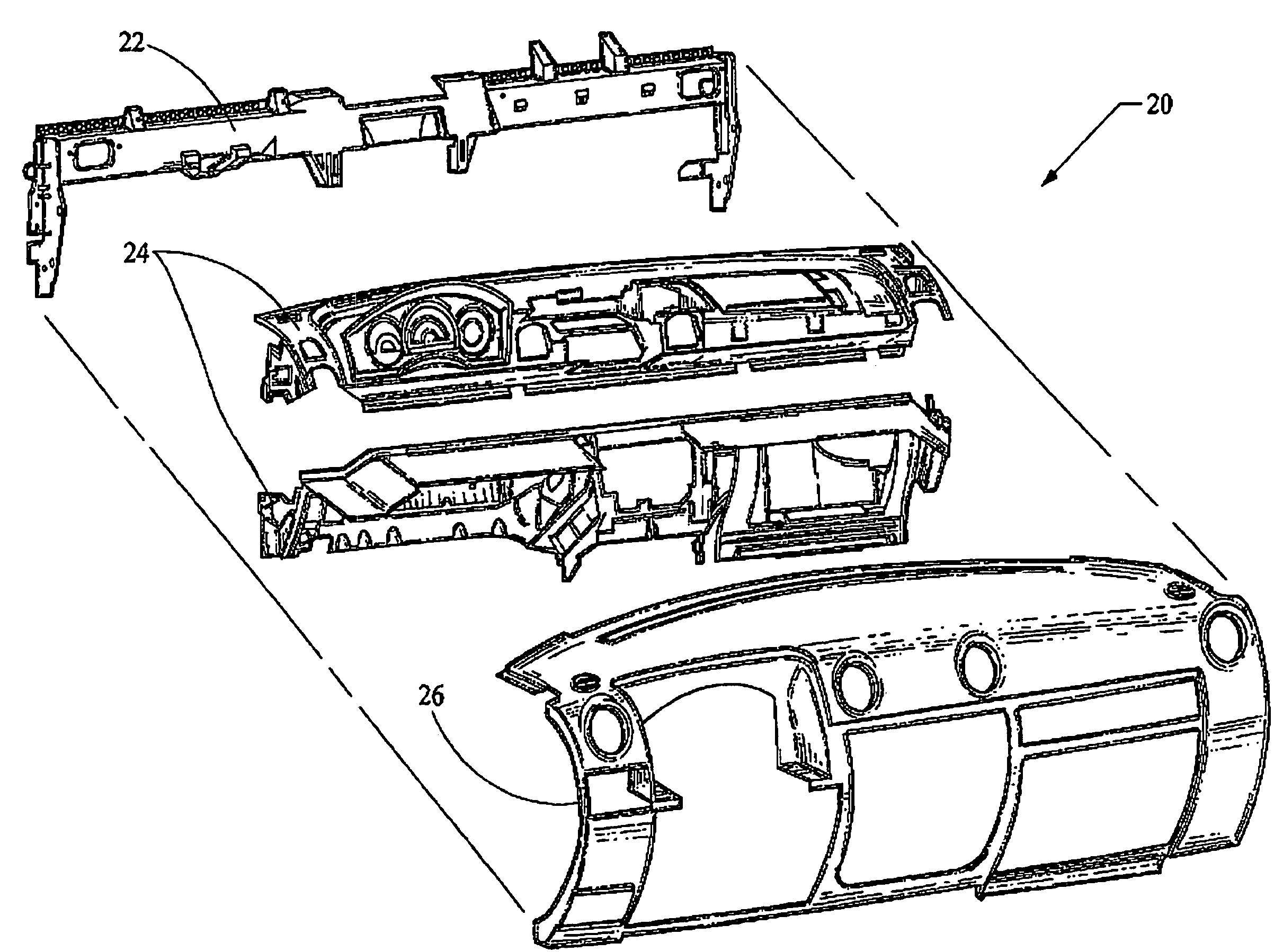
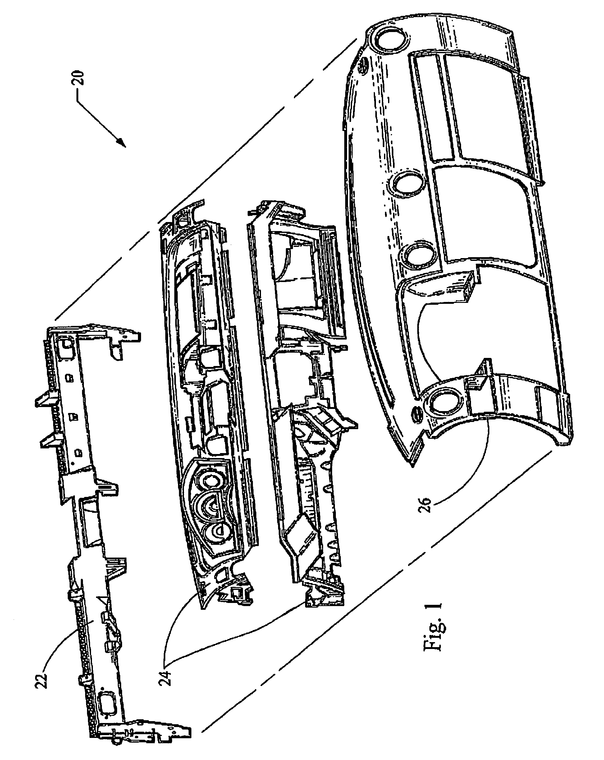
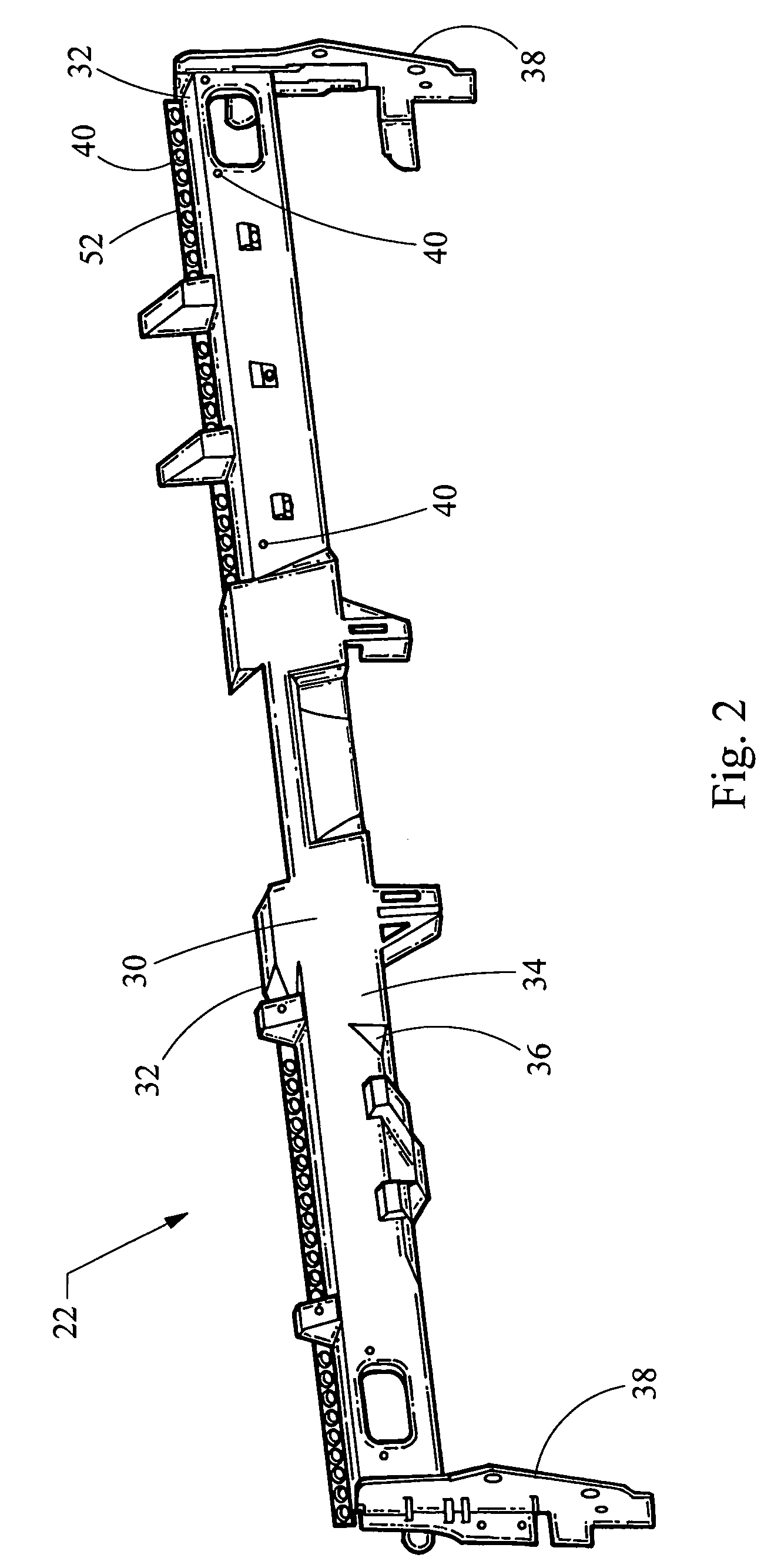
[0015]Turning now to the figures, FIG. 1 depicts an exploded view of a cockpit assembly 20 for a motor vehicle (not shown) constructed in accordance with the teachings of the present invention. The cockpit assembly generally includes a backbone 22, an intermediate support member 24, and an instrument panel 26. The backbone 22 is preferably constructed of a cast alloy such as a magnesium alloy. In this manner, the backbone may be structured to include unique attachment features which permit injection molding of the intermediate support member 24 to the cast alloy backbone 22. Furthermore, the cockpit assembly 20 allows the intermediate support member to be constructed of a strong and durable plastic material, preferably selected from the group consisting of nylon, glass filled polypropylene, styrene, polycarbonate or blends thereof, such as ABS / PC. As such, the plastic material of the intermediate support member 24 generally has higher tensile strength and greater rigidity than the p...


PUM


Abstract

A cockpit assembly generally includes a cast alloy backbone, an intermediate plastic support member, and an instrument panel. The cast alloy backbone extends laterally and defines attachment features. The intermediate support member provides structural support to the various devices of the cockpit assembly, and is connected to the backbone through molding of the plastic around the attachment features. The instrument panel is connected to the support member and defines an interior surface exposed to the passenger compartment of the vehicle.

Description

FIELD OF THE INVENTION[0001]The present invention relates generally to a cockpit assembly for a motor vehicle, and more particularly relates to providing structural support for functional devices in a cockpit assembly.BACKGROUND OF THE INVENTION[0002]In a typical cockpit assembly for a motor vehicle, a metal cross-car beam is augmented with a plurality of structural extensions for supporting various functional devices within the cockpit assembly. Such functional devices in the cockpit assembly include center stack devices (i.e., informational, communication or entertainment devices), HVAC devices and related air handling structures, wire harnesses, airbags, an instrument cluster, glove boxes and the like. The structural support for such devices is provided by various metal extensions such as brackets, rods and other add-on structures which are used to mount these devices in the cockpit assembly. The cockpit assembly is closed off to the passenger compartment by an instrument panel. ...

Claims


Application Information

Patent Timeline
Patent Type & Authority Patents(United States)
IPC IPC(8): B62D25/14
CPCB62D25/145B60R2011/0005
Inventor VANDER SLUIS, DANIEL R.CAIE, JAMES D.CAMILLETTI, III, JOSEPH A.
Owner VISTEON GLOBAL TECH INC
Learn More